Please watch video in (picture-in-picture) mode to take advantage of timestamps on each key point below
install TENDONs
In this step, the tendons are attached to all the digits and the inner palm pieces are screwed into place.
Tools needed:
1. Small flat blade and small crosshead screwdriver.
2. Tweezers.
3. Scissors, craft knife or Stanley knife.
4. Side cutters or pliers to grip pins.
Parts needed:
1. 0.45mm (.018") diameter string - Braided fishing line is suitable, Sufix 832 (80lbs) is the best.
The tendons are simply loops of string that pass through a hole in the servo horn and over a pin in the tip of each digit.
The loop is formed by a figure-8 knot (16.52) and defined by the distance from this knot to the end of the loop with the string pulled tight.
Summary of tendon lengths:
1. Little finger = 160mm
2. Ring finger = 160mm
3. Index finger = 188mm
4. Fore finger = 146mm
5. Thumb = 105mm
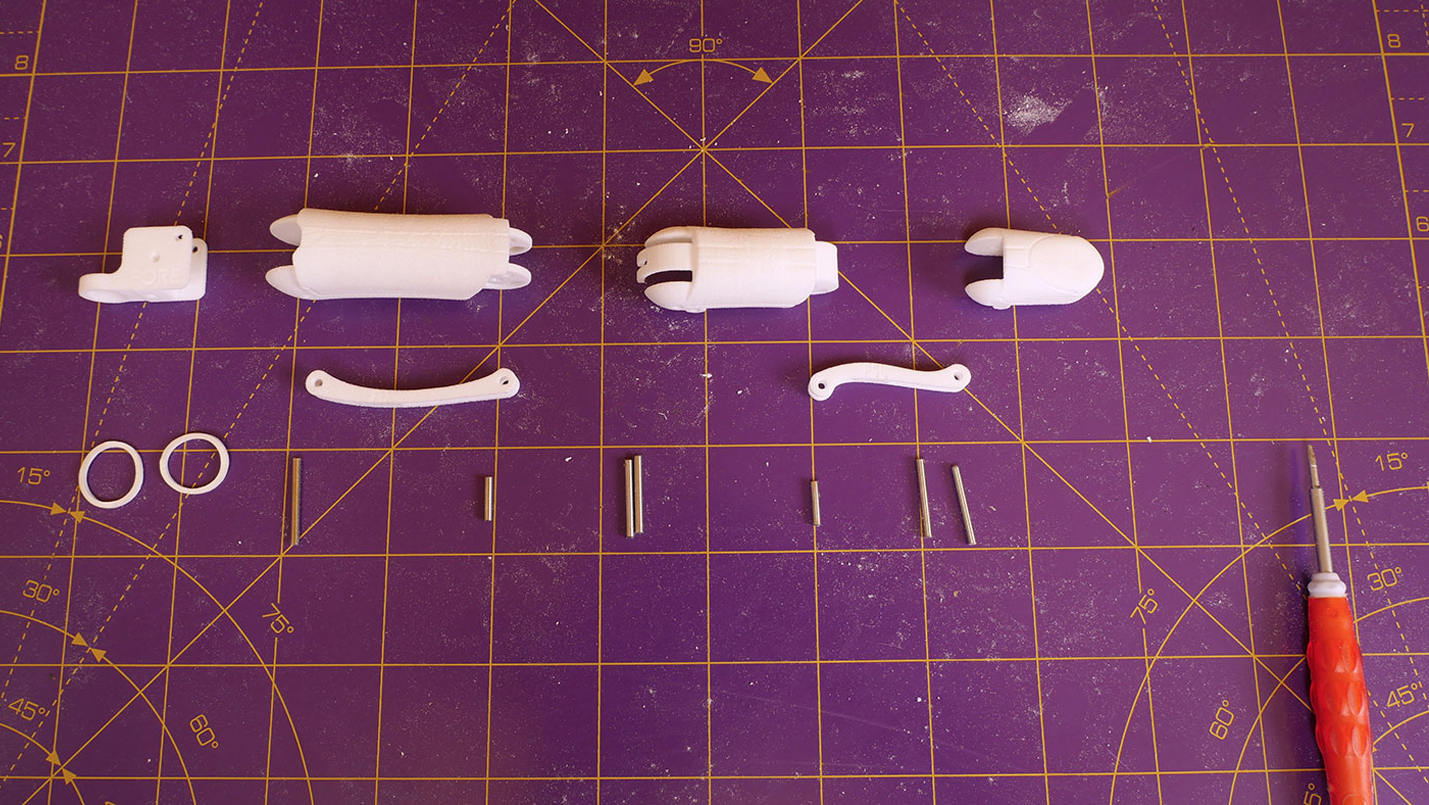
There are two inner palm pieces – a small one just for the little finger and a larger one for the other three fingers which also houses the camera.
The finger tendons can most easily be set once the inner palms are assembled, however assembling the inner palm makes access to servo 10 (thumb tendon) very awkward.
Thus the recommended way to proceed is first to assemble the little finger completely to gain familiarity with the procedure.
Then set the tendon up for the thumb to allow the inner palm to be attached.
Then set up the remaining finger tendons and the camera before finally attaching the thumb.
Prepare both inner palms
In step 2, you should have already fitted ptfe liners to the tunnel in the little finger inner palm and the three tunnels in the inner palm.
If you forgot, add these and the short vertical length of ptfe in the middle of inner palm for the thumb tendon (2.34 - 3.08).
Make sure that the little finger inner palm fits neatly into place over the knuckle pin and the little finger servos - it should be flush against the servo flanges (9.32 - 9.55).
Make sure that the inner palm fits neatly into place (3.09 - 4.32).
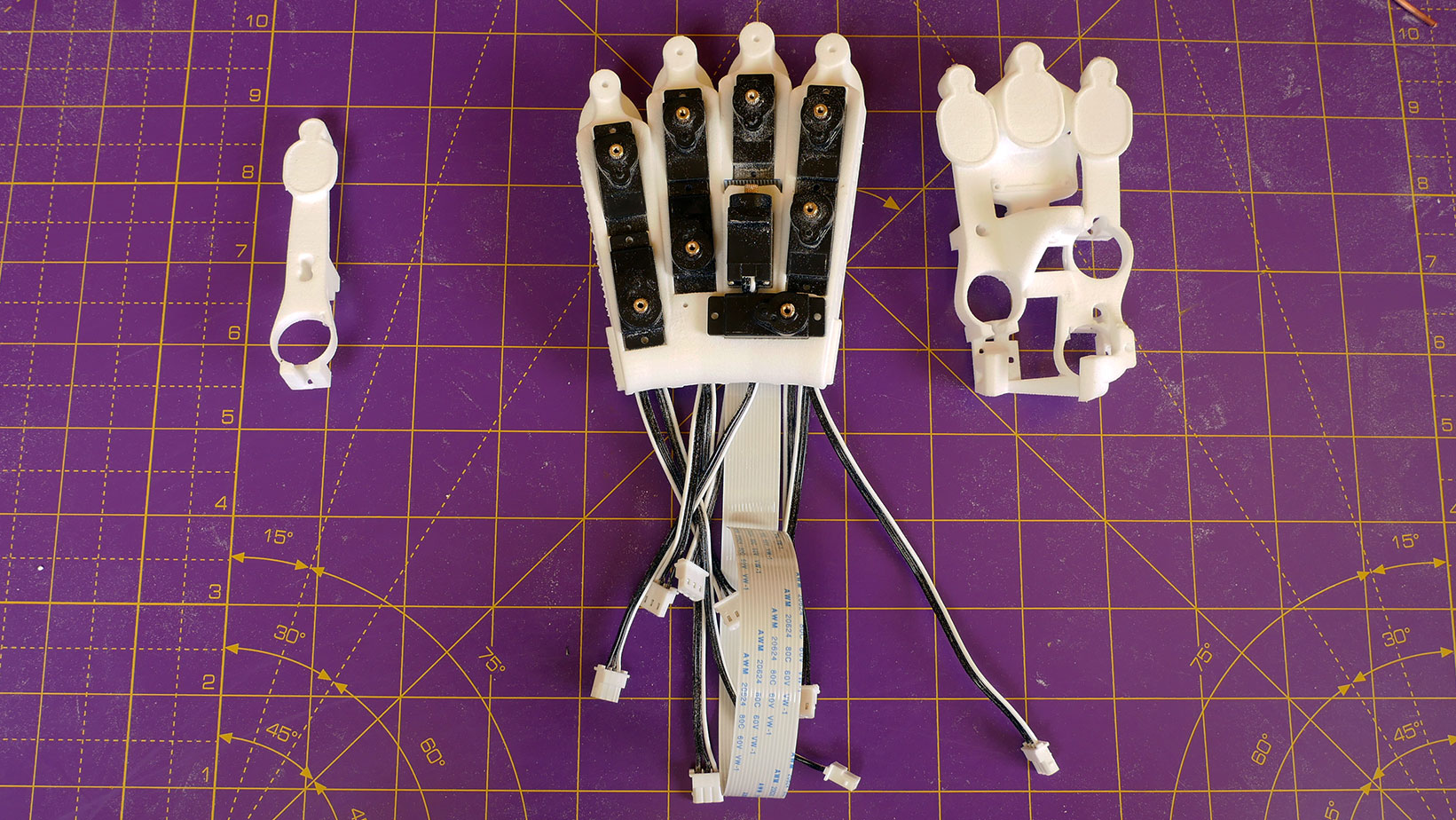
The little finger inner palm and the inner palm fit over the servos in the palm and secure them with the screws supplied with the SCS009 servos.
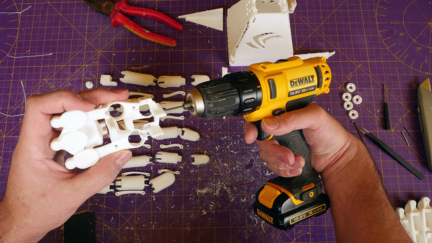
Before attempting to screw the inner palms into position it is a good idea to open up the holes with the screws by themselves (9.13).
Some of the screws are set in deep recesses and can be very awkward to access once the inner palm is in place - it is recommended to fit screws to these holes before assembling the inner palms.
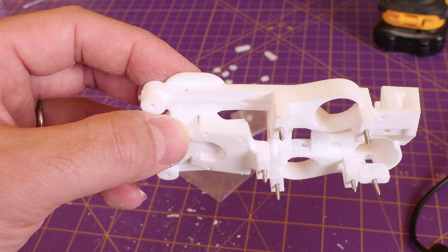
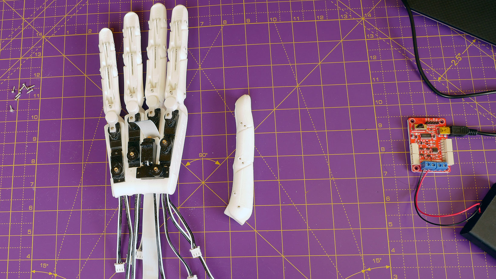
Insert screws in the three holes in the little finger palm so they protrude from the bottom, making sure to clean out any support material that might be in the bottom of the screw holes (10.05 - 10.40).
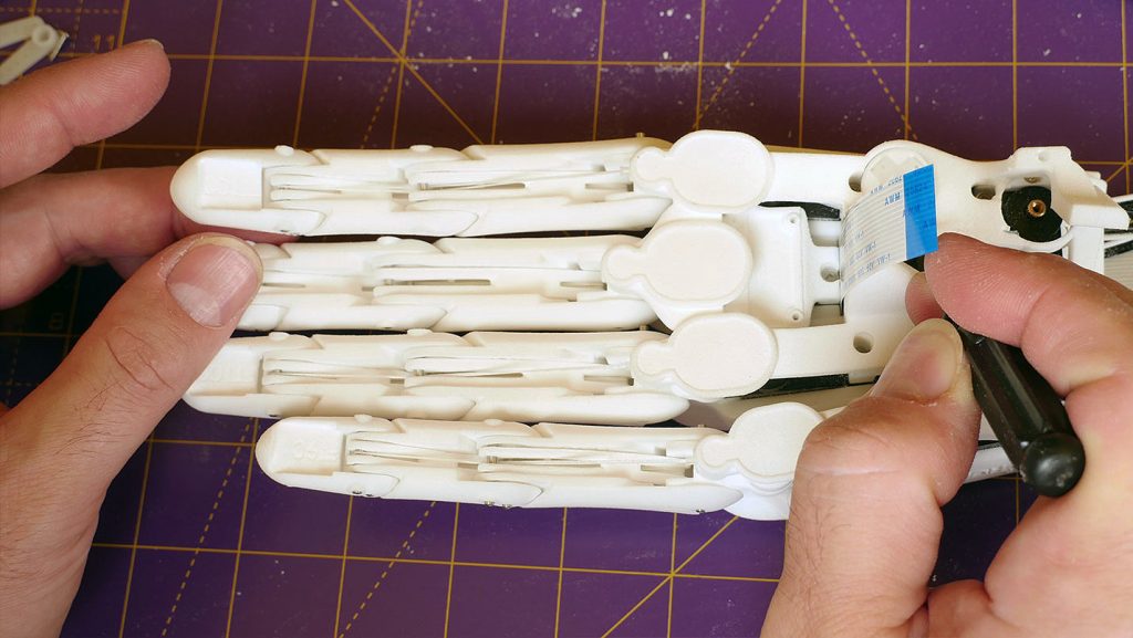
Repeat for the seven recessed screws in the inner palm (19.30 - 20.12).
Note the seventh screw is still to go in the top right hole in the photo below:
Place the little finger palm into position and carefully screw down - make sure not to over-tighten the screws! (10.40 - 11.15)
For the entire procedure to assemble the tendon for the little finger see the video (16.40 - 19.18).
The tendons are simply wound up by the servo winch when the servo turns.
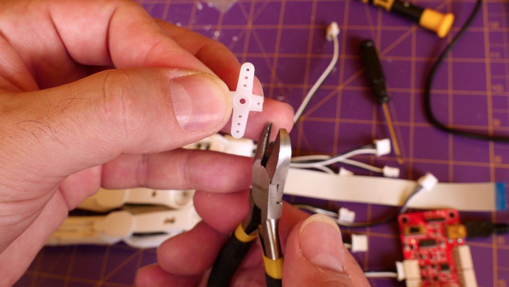
First trim the cross shaped servo horn supplied with the servos so it fits inside a servo winch (11.21-12.00).
Trim about half a mm beyond the first hole on each arm of the cross.
Check that the trimmed horn fits inside the servo winch – it should press in completely flush.
Make little finger tendon
The tendon is simply a measured loop of string (1.48) fastened with a knot (16.52) to the servo horn.
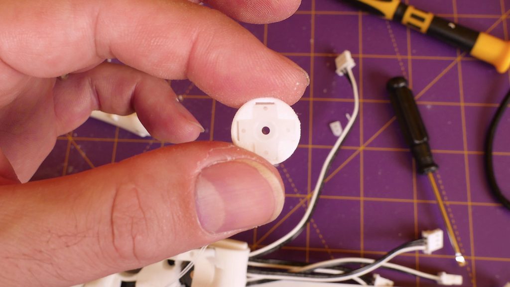
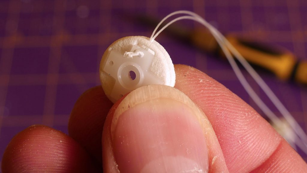
The printed servo winch that receives the servo horn is circular to ensure that the tendon retracts evenly as the servo turns.
Simply pull a length of tendon over the end of a ruler and mark it on both sides at the correct distance.
For the little finger mark the tendon at 160mm.
Then tie a knot - a simple figure-8 knot works well (16.52) so that the marks are just where the knot begins - try to be accurate - it's ok to be a little too long but not to be too short or the finger will not extend fully.
The distance from the knot to the end of the loop should be the distance given above - so in the loop itself there is twice that length of tendon.
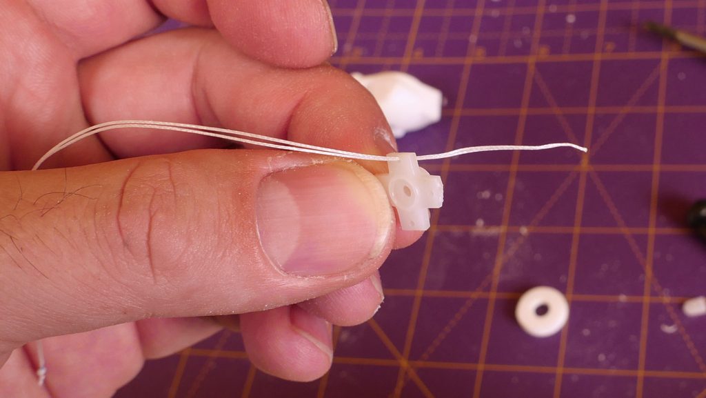
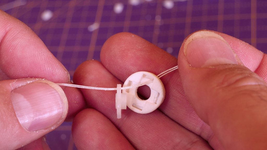
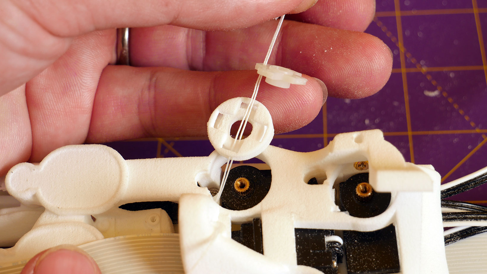
Then squeeze the end of the loop flat and thread it through a hole in one of the arms of the servo horn (17.13).
Then pass the looped end through the servo winch and press the winch and the horn together (17.22).
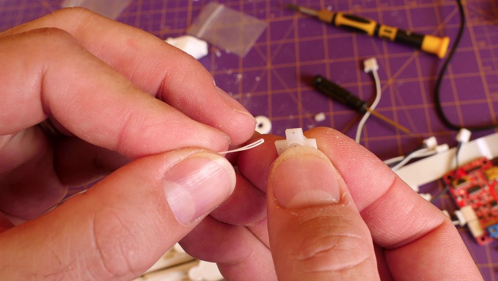
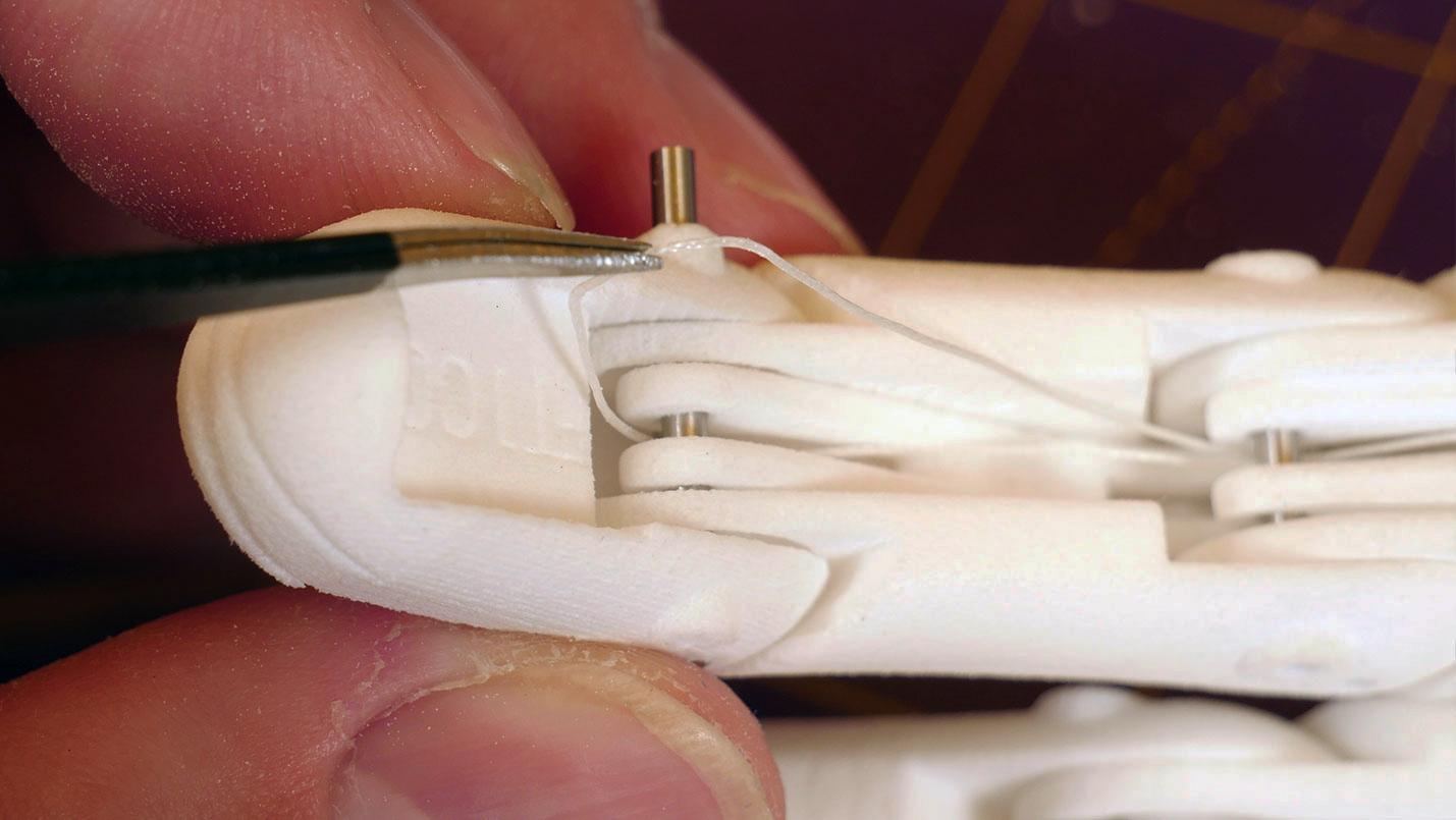
The photos are for the fore finger tendon but the procedure is the same for all the fingers.
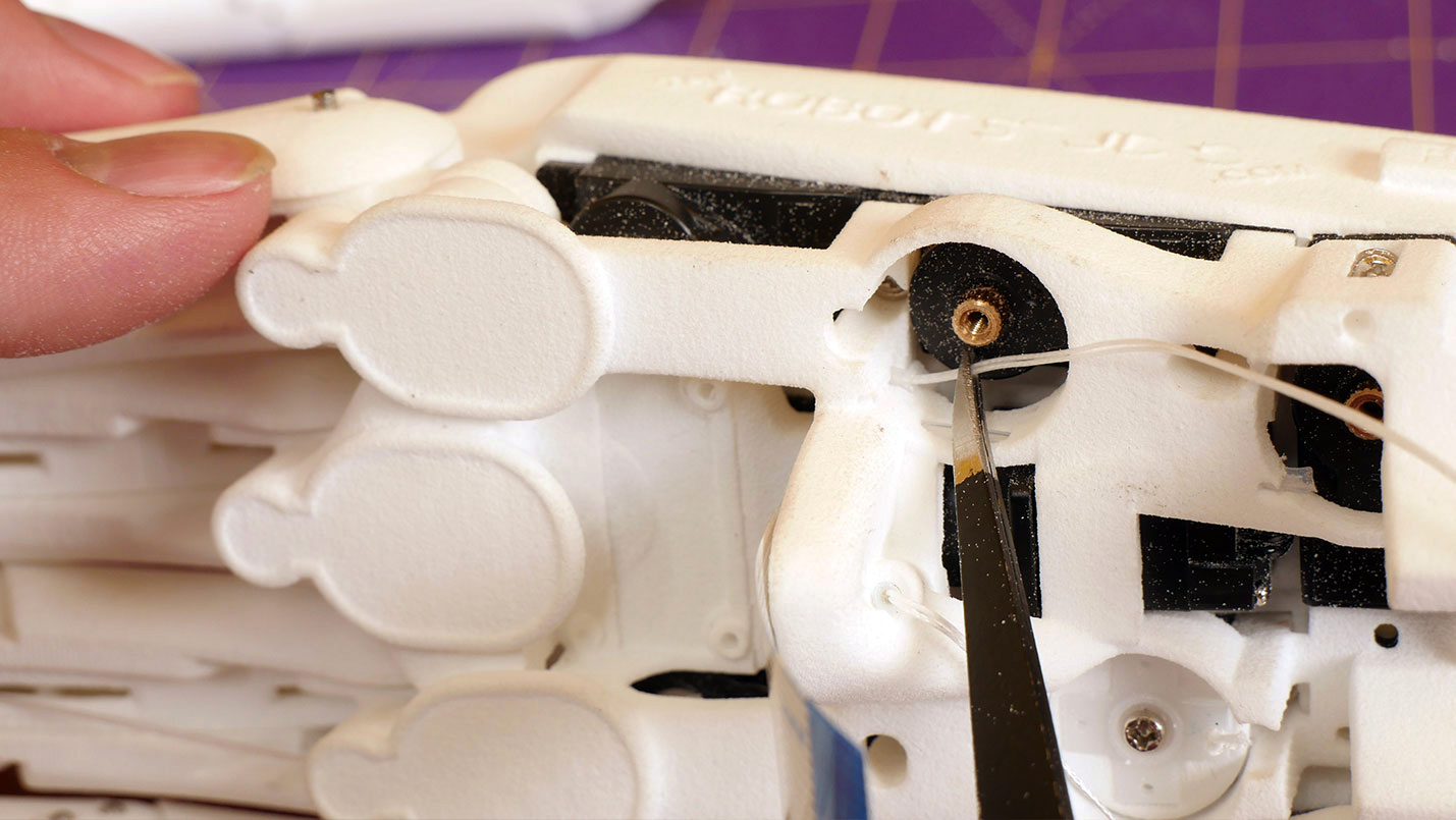
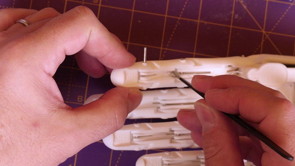
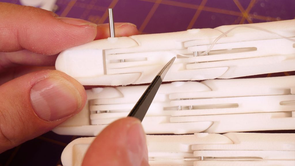
Starting at the servo end, pass the looped end through the ptfe in the tendon tunnel (17.34).
Capture the loop around the last pin in the finger (18.15).
Fit servo winch assembly to servo
Make sure the servo is in the correct position.
With the finger at full extension rotate the servo horn until the tendon just goes tight (18.13).
Press the servo horn on to the servo to mate the splines (18.59).
Check the finger flexes by driving the servo from the FT GUI and then retain the winch assembly with a servo horn screw (19.09).
To fit the tendons for the other fingers the other inner palm piece must be fitted.
However, doing so makes access to servo 10 (thumb tendon) very awkward.
So first it is necesary to set the servo winch in position on servo 10.
Test Fit tendon to thumb
Make sure the servo is in the correct position.
The thumb tendon servo winch is hard to access once the inner palms are fitted so it is easier to fit the servo winch for the thumb tendon before assembling the rest of the fingers.
Make a loop of tendon 105mm long between the knot (16.52). and the end of the loop (1.48). and assemble it with a trimmed servo horn and servo winch in the same way as for the little finger.
Check that servo 10 has position 0 with the FT GUI (2.24).
Wind the tendon anti-clockwise around the servo winch for about half a turn and fit the servo winch assembly to servo 10 (2.31).
Pass the loop end of the thumb tendon through the ptfe in the inner palm and fit the inner palm in position making sure it is flush to all the servos (3.06).
Put the thumb in position and check that the tendon is just long enough to allow the thumb to fully extend (4.32) - exactly the same as for the little finger.
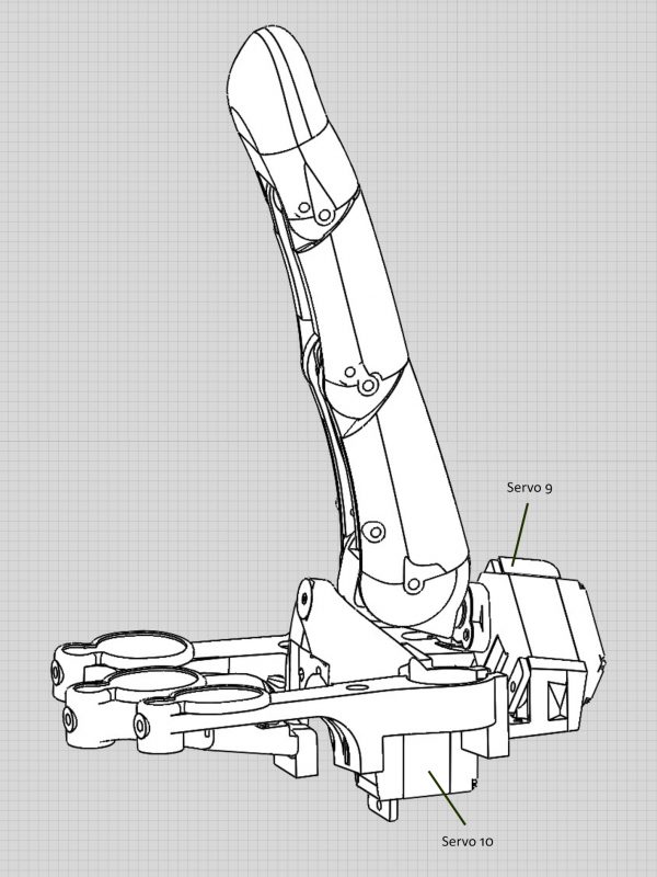
The thumb position is fixed by servo 9 and a pin through the inner palm and the thumb knuckle cross (6.20).
Although not shown in the video make certain of the thumb tendon length by passing the tendon under the pin in holes D1 and F and securing the loop over pin H - i.e. attach the tendon as it will be in the final assembly.
Retain the servo winch assembly for the thumb tendon with a servo horn screw (8.26).
Fit inner palm
Make sure the screws are still in position in the seven recessed holes in the inner palm.
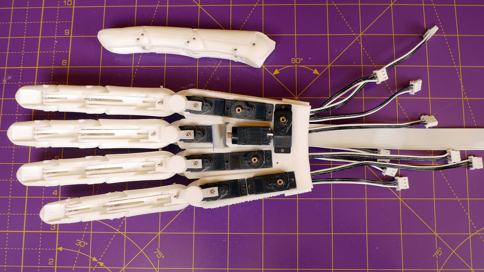
Pass the thumb tendon and the camera cable through the inner palm (20.13).
Carefully place the inner palm into position and screw each of the screws into place taking particular care not to over tighten and break the threads in the holes at the overlap of servo 3 and 4 and servo 7 and 8 (20.30).
Assemble ring and fore finger tendons – not the Index finger
The tendon of the index finger passes above the camera - leave this finger to last as it is easier to fit after mounting the camera.
The procedure to assemble the ring and fore finger tendons is exactly the same as for the little finger.
The only differences are in the lengths of the tendon loops and the directions that the tendon servos rotate.
Make a loop of tendon as listed below:
1. Ring finger 160mm
2. Fore finger 146mm
Repeat the steps above to attach the ring and fore fingers.
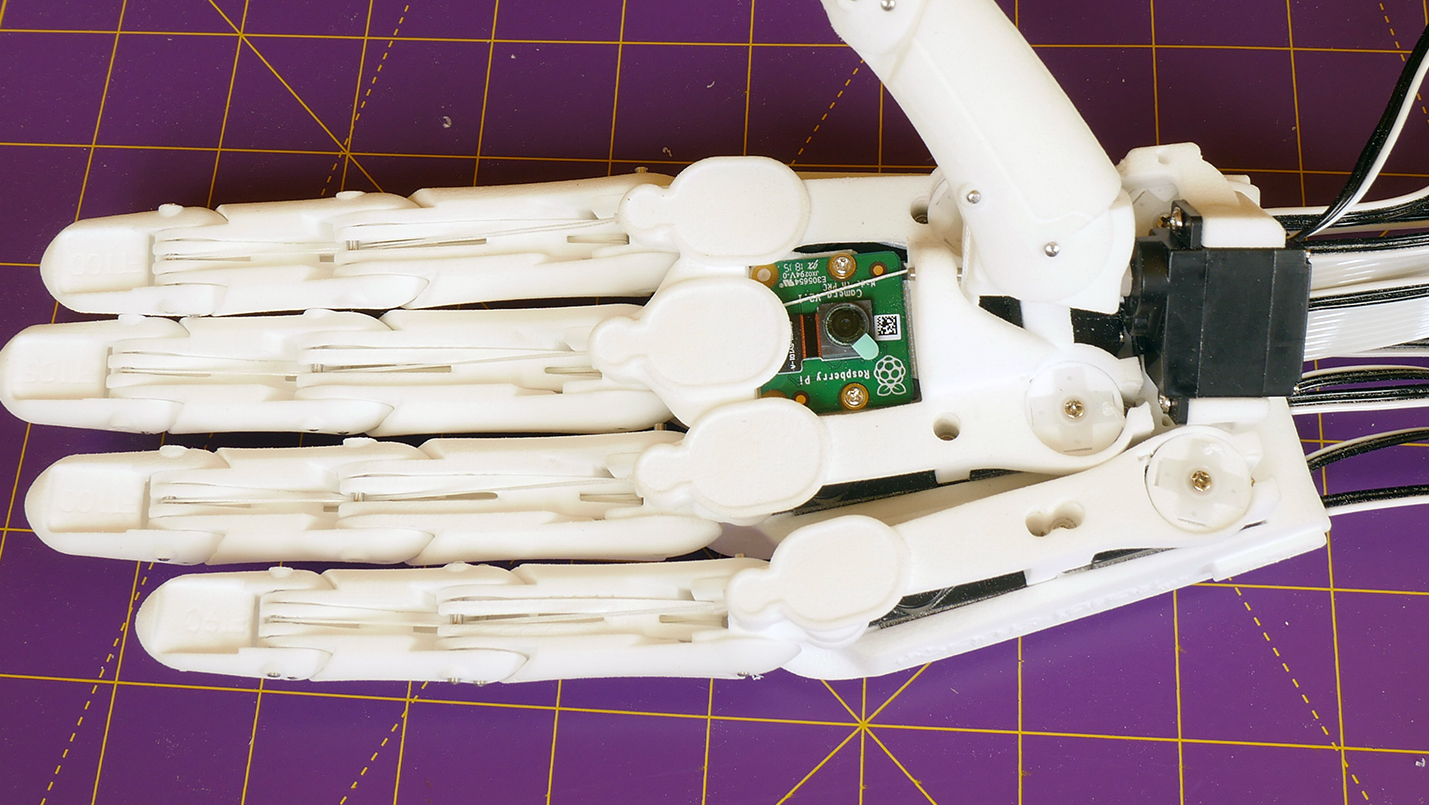
Attach the camera to the end of the cable protruding from the inner palm (24.14).
Insert the non-cable end of the camera at an angle under the finger pads (24.32).
Carefully push the camera into a flat position whilst gently pulling the camera cable out the wrist end to minimise sharp bends (24.39).
Secure the camera with two small screws that come supplied with the SCS15 wrist servo (25.05).
Fit index finger tendon
The procedure to attach the index finger tendon is the same as for the other fingers (21.46 - 24.13).
The tendon length for the index finger is 188mm.
Attach the thumb
The servo horn for the thumb roll servo (9) is a tight push-fit into the rectangular hole in the top of the thumb knuckle cross.
Power up the thumb roll servo (9) and set to position 512.
Attach the horn to the servo so that it is aligned to the centre of the thumb’s final roll range when the servo is held in its final position in the inner palm.
Trim the servo horn so that it will not protrude from the hole and push it firmly
into the thumb knuckle cross.
This is how it is shown in the video - with the horn attached to the servo first.
An alternative method is to:
1. Drop the servo horn screw into the recess upside down.
2. Force the trimmed servo horn in with a pair of pliers.
3. Screw the servo horn in place by passing a screwdriver up the thumb roll
pin hole in the thumb knuckle cross.
Clean the screw holes in the inner palm that secure servo 9 by fully screwing in and removing the screws a few times (25.24).
Put thumb roll servo (9) in its final position with a 24mm pin through the inner palm and thumb knuckle cross and screw in place (26.01).
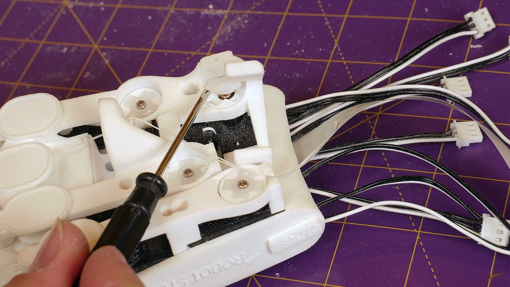
The deeper screw towards the centre of the hand is a little awkward and may need to be held in place with tweezers at the start of screwing in (27.10).
Thread the tendon through the thumb and secure at the final pin (27.17).
Note the thumb tendon passes over the thumb roll pin towards the center of the hand.
Time to move on to the last step and fit the hand to the base, step 7
Step 1
Step 3
Step 3
Step 4
Step 5
Step 6
Step 7
We use cookies on our website to give you the most relevant experience by remembering your preferences and repeat visits. By clicking “Accept All”, you consent to the use of ALL the cookies. However, you may visit "Cookie Settings" to provide a controlled consent.
This website uses cookies to improve your experience while you navigate through the website. Out of these, the cookies that are categorized as necessary are stored on your browser as they are essential for the working of basic functionalities of the website. We also use third-party cookies that help us analyze and understand how you use this website. These cookies will be stored in your browser only with your consent. You also have the option to opt-out of these cookies. But opting out of some of these cookies may affect your browsing experience.
Necessary cookies are absolutely essential for the website to function properly. These cookies ensure basic functionalities and security features of the website, anonymously.
Cookie
Duration
Description
cookielawinfo-checkbox-analytics
11 months
This cookie is set by GDPR Cookie Consent plugin. The cookie is used to store the user consent for the cookies in the category "Analytics".
cookielawinfo-checkbox-functional
11 months
The cookie is set by GDPR cookie consent to record the user consent for the cookies in the category "Functional".
cookielawinfo-checkbox-necessary
11 months
This cookie is set by GDPR Cookie Consent plugin. The cookies is used to store the user consent for the cookies in the category "Necessary".
cookielawinfo-checkbox-others
11 months
This cookie is set by GDPR Cookie Consent plugin. The cookie is used to store the user consent for the cookies in the category "Other.
cookielawinfo-checkbox-performance
11 months
This cookie is set by GDPR Cookie Consent plugin. The cookie is used to store the user consent for the cookies in the category "Performance".
viewed_cookie_policy
11 months
The cookie is set by the GDPR Cookie Consent plugin and is used to store whether or not user has consented to the use of cookies. It does not store any personal data.
Functional cookies help to perform certain functionalities like sharing the content of the website on social media platforms, collect feedbacks, and other third-party features.
Performance cookies are used to understand and analyze the key performance indexes of the website which helps in delivering a better user experience for the visitors.
Analytical cookies are used to understand how visitors interact with the website. These cookies help provide information on metrics the number of visitors, bounce rate, traffic source, etc.
Advertisement cookies are used to provide visitors with relevant ads and marketing campaigns. These cookies track visitors across websites and collect information to provide customized ads.