Congratulations! the hard bit is done, mechanically speaking at least.
Now all you have to do is plug all the cables in, screw it all together and fire up the software!
Tools needed:
1. A Windows PC.
2. Crosshead screwdriver.
3. Craft knife or Stanley knife.
4. Side cutters or pliers to grip pins.
5. 2mm drill and means to turn it.
Parts needed:
1. Assembled hand.
2. FE-URT board and supplied USB cable.
3. Jetson nano with latest Jetpack installed.
4. 5v power supply for the Jetson and a jumper connector.
5. 6v power supply for the servos and a barrel jack to fit power supply with flying leads.
6. Insulating tape – wrapping the servo connector boards in insulating tape is a very good idea not shown in the video.
Assuming the physical layer is done correctly then everything which follows should work first time.
In practice, getting robots to run is almost always an exercise in the art of debugging – the best advice anyone can give you is to always start debugging with the physical layer – is it plugged in correctly? – solves over 75% of support calls and always a pleasure to find it isn’t working for an easy reason to fix!
Otherwise check each component part and only put together systems from parts you are sure are fully working.
Once you have a working system change or add only one thing at a time and always make sure you can get back to a position where everything worked as expected.
Robots are much harder to debug than code alone as faults may arise in mechanical, electrical or computational systems that interact with the other layers in ways that are unexpected and hard to predict.
At this stage you need to be confident that all the assembled parts are working reliably, here’s a quick checklist:
1. Plug the hand in and make sure you can command the fingers from the FT GUI – double check that each digit closes for an even node ID and wags from side to side for an odd. Remember that tendon servos 6 and 8 wind in the opposite direction so the finger is open for large numbers and closes for small.
2. Check the insulation on the servo connector boards.
3. Make sure the Jetson will boot up and that the latest Jetpack is installed.
4. Make sure the camera works when plugged into the Jetson. (more info)
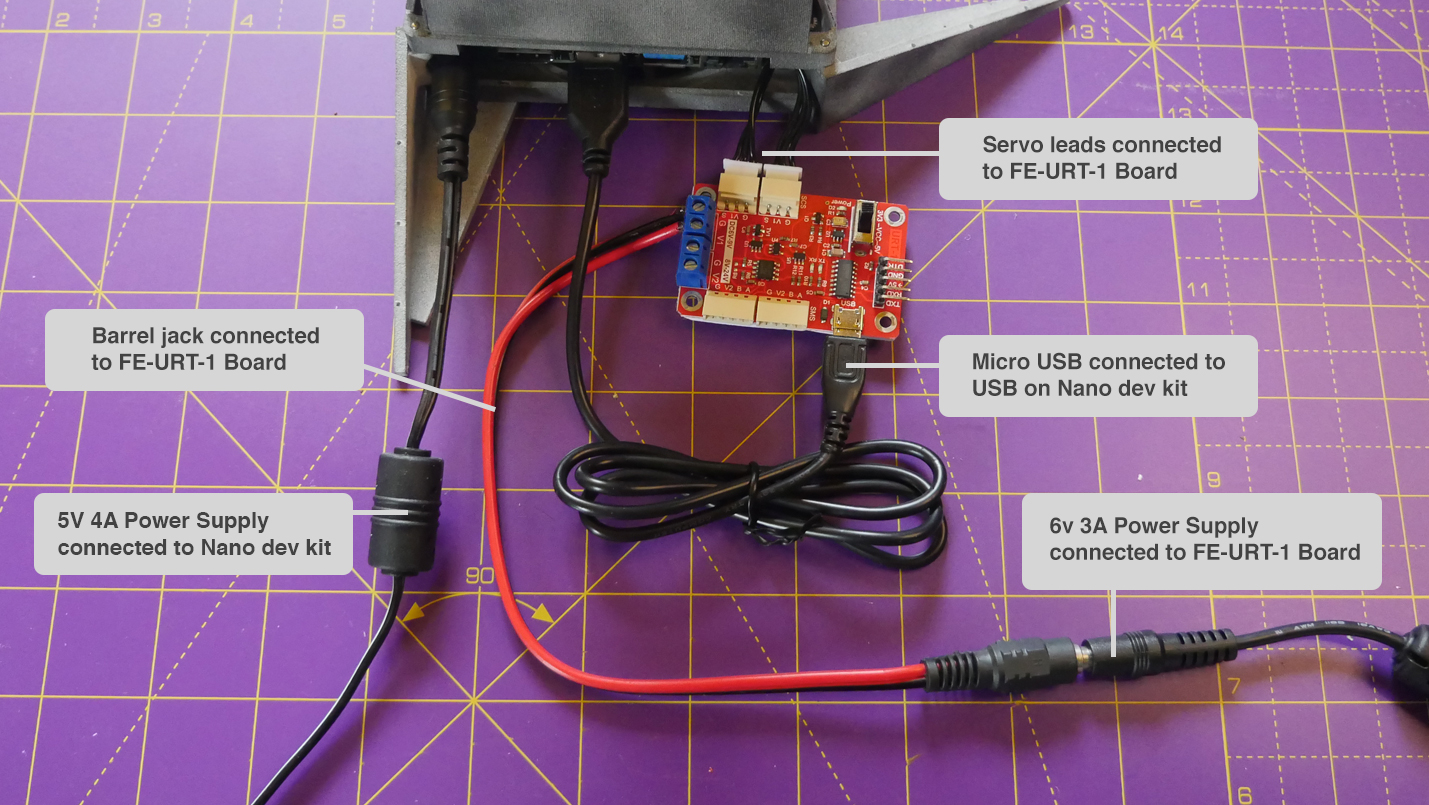
5. Have a quick check that the power supplies are plugged in to the right sockets on the Jetson and the FE-URT board.
Onwards!
Connect the wrist servo to the FE-URT board and set the position to 512 (1.22).
Attach the driven servo horn, but not the wrist bracket, to the servo such that the holes are aligned with the fore bracket pointing directly away from the servo (2.03).
Clean the wrist brackets and note which is the fore finger and which is the little finger side – the names are written on the bottom of the rectangular recess where the brackets clip to the palm (2.10).
Attach the undriven servo horn, but not the wrist bracket, to the servo. Please note that although shown in the video it is not recommended to screw the servo horn in place (3.16).
Fit the wrist brackets to the palm making sure the fore and little finger sides are respected (4.34). Please note that this is not how it is shown in the video so skip straight to (5.02) for the second wrist bracket.
Divide the servo wires that emerge from the hand evenly and push the servo into position between the wrist brackets (5.04).
The driven side is the fore finger side.
Screw the wrist brackets to the servo horns and the wrist brackets to the palm (5.15).
Check that the wrist moves under control from the FT GUI (6.27).
Attach all the servo wires together and test that all the servos work using the servo range option in the FT GUI (6.33).
When all the fingers move it should look like this (10.04) and (10.43).
Prepare the base box by removing all printing supports and drilling out all the holes (11.16).
Place the nano into bottom of base box (13.42).
The sides of the box if printed by SLS or MFJ are connected by plastic hinges (14.03). Should these break there are also holes provided to replace these hinges with pins.
For FDM printed base boxes the sides are hinged only by pins.
Screw the nano to the base box (14.26).
Remove the flat plates in the corners labelled "REMOVE" (15.01).
The fold-out feet are pinned at each corner and interlock neatly to the sides of the box when folded away (15.03).
The feet are labelled "FRONT/BACK" and "SIDES" which corresponds to the folded away position. The back of the box is where the sockets on the Jetson can be accessed.
Clean the pin holes and attach the feet with 24mm long pins (16.16).
Release the latch on the camera socket through the sides of the base box (20.53) and plug in the camera cable to the nano (22.00).
Connect the jumper to j48 pins on the Nano development kit to enable DC power.
Wrap the servo connector boards in insulating tape!!
Screw the wrist servo (11) to one of the the pyramidal sides of the base box – note the screw pattern is different on each side (23.12).
Connect the USB to serial adaptor to the servo pins on the FE-URT board (not shown in the video).
Carefully pack the mass of servo wires into the base box and screw the other side to the wrist servo (23.45).
Secure the front and back of the base box pyramid to the sides with pins pushed in from the top (27.54).
Press the inner palm pads into position on the inner palm.
Next it’s time to connect the power and the servo controller board.
Programming the hand for gesture and mimic.
| Cookie | Duration | Description |
|---|---|---|
| cookielawinfo-checkbox-analytics | 11 months | This cookie is set by GDPR Cookie Consent plugin. The cookie is used to store the user consent for the cookies in the category "Analytics". |
| cookielawinfo-checkbox-functional | 11 months | The cookie is set by GDPR cookie consent to record the user consent for the cookies in the category "Functional". |
| cookielawinfo-checkbox-necessary | 11 months | This cookie is set by GDPR Cookie Consent plugin. The cookies is used to store the user consent for the cookies in the category "Necessary". |
| cookielawinfo-checkbox-others | 11 months | This cookie is set by GDPR Cookie Consent plugin. The cookie is used to store the user consent for the cookies in the category "Other. |
| cookielawinfo-checkbox-performance | 11 months | This cookie is set by GDPR Cookie Consent plugin. The cookie is used to store the user consent for the cookies in the category "Performance". |
| viewed_cookie_policy | 11 months | The cookie is set by the GDPR Cookie Consent plugin and is used to store whether or not user has consented to the use of cookies. It does not store any personal data. |