Please watch video in (picture-in-picture) mode to take advantage of timestamps on each key point below
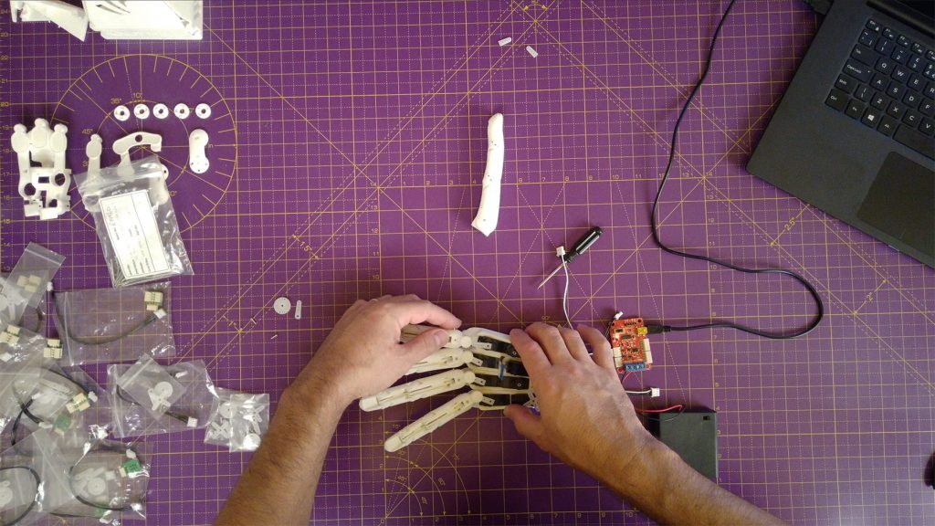
Attach fingers at knuckle servos
In this step, the fingers and thumb are connected to the knuckle servos and attached to the palm section.
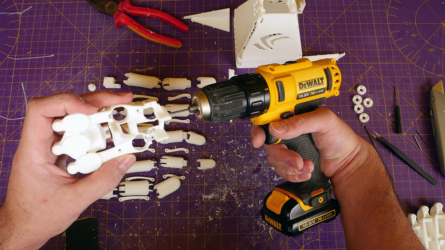
Tools needed:
1. Small cross-head screwdriver.
2. Tweezers.
3. Craft or Stanley knife (optional – may be needed to fit the servo horn in the thumb knuckle cross of SLS prints).
4. Pair of pliers (optional – may be used to force the servo horn into the thumb knuckle cross).
5. Windows PC with the Feetech FT GUI.
6. FE-URT linker board.
7. 6v dc power supply or battery pack.
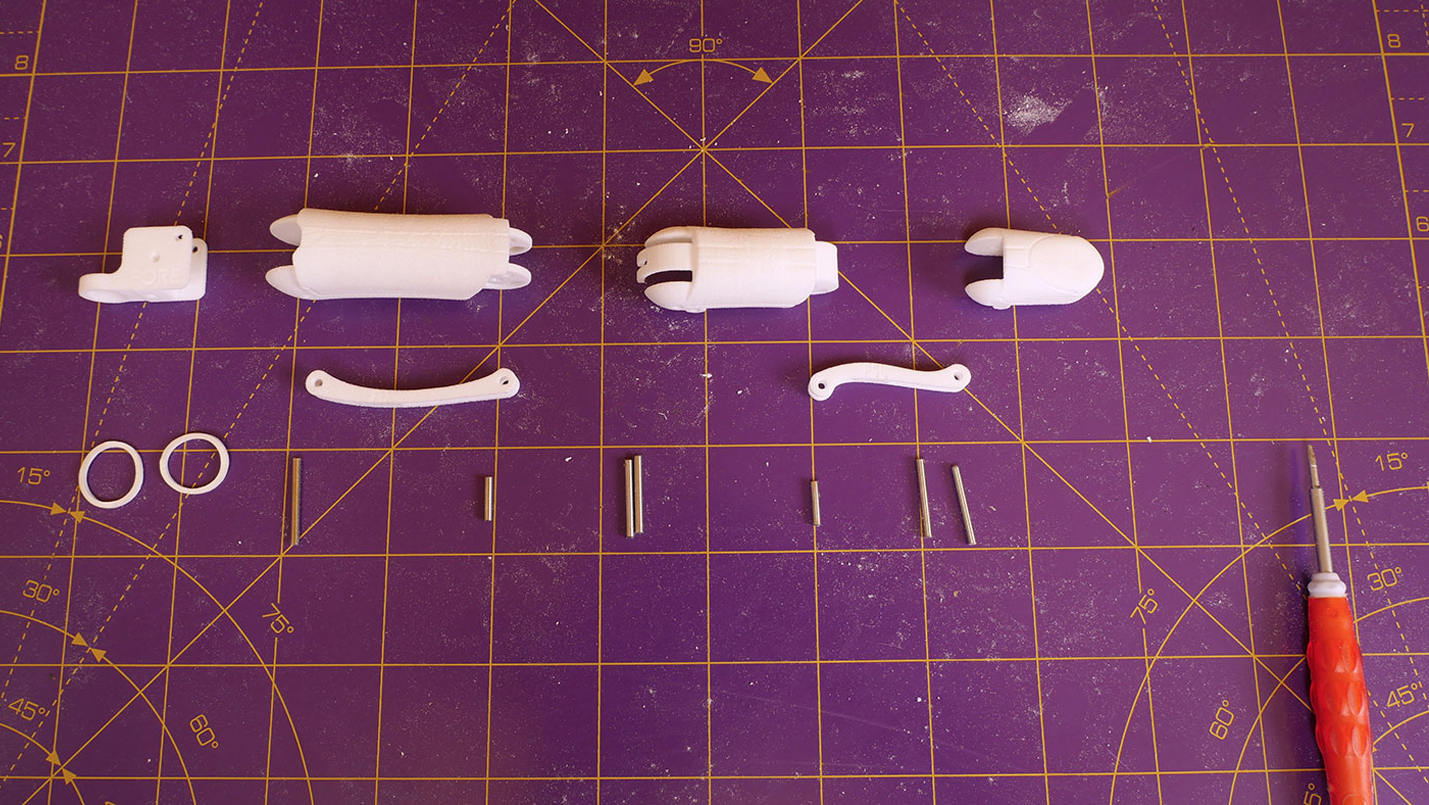
Parts needed:
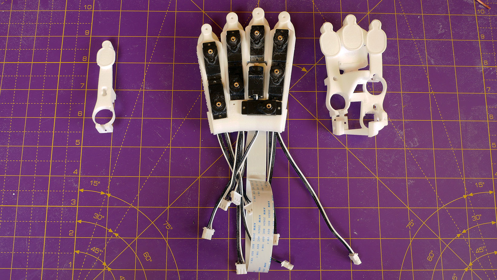
1. Assembled fingers and thumb.
2. Palm with installed servos.
3. 24mm x 2mm diameter ground steel pins.
Attach Fingers at knuckle servos
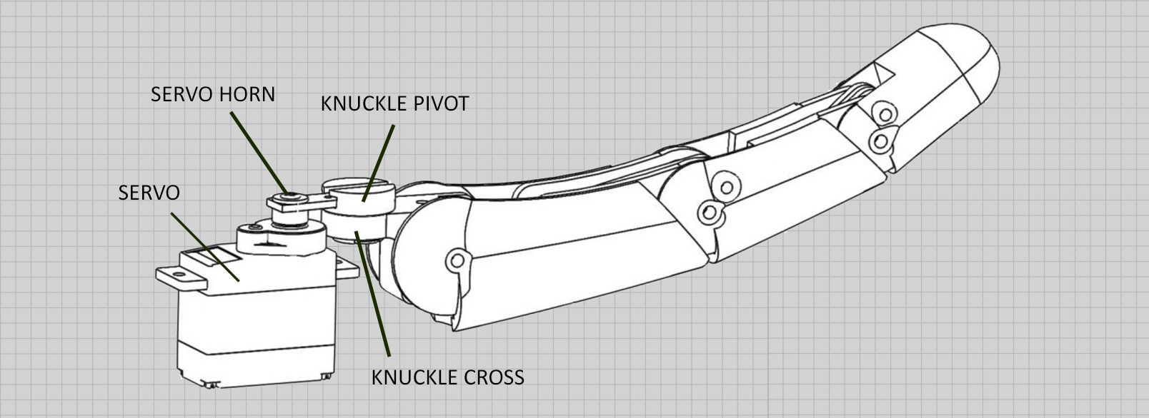
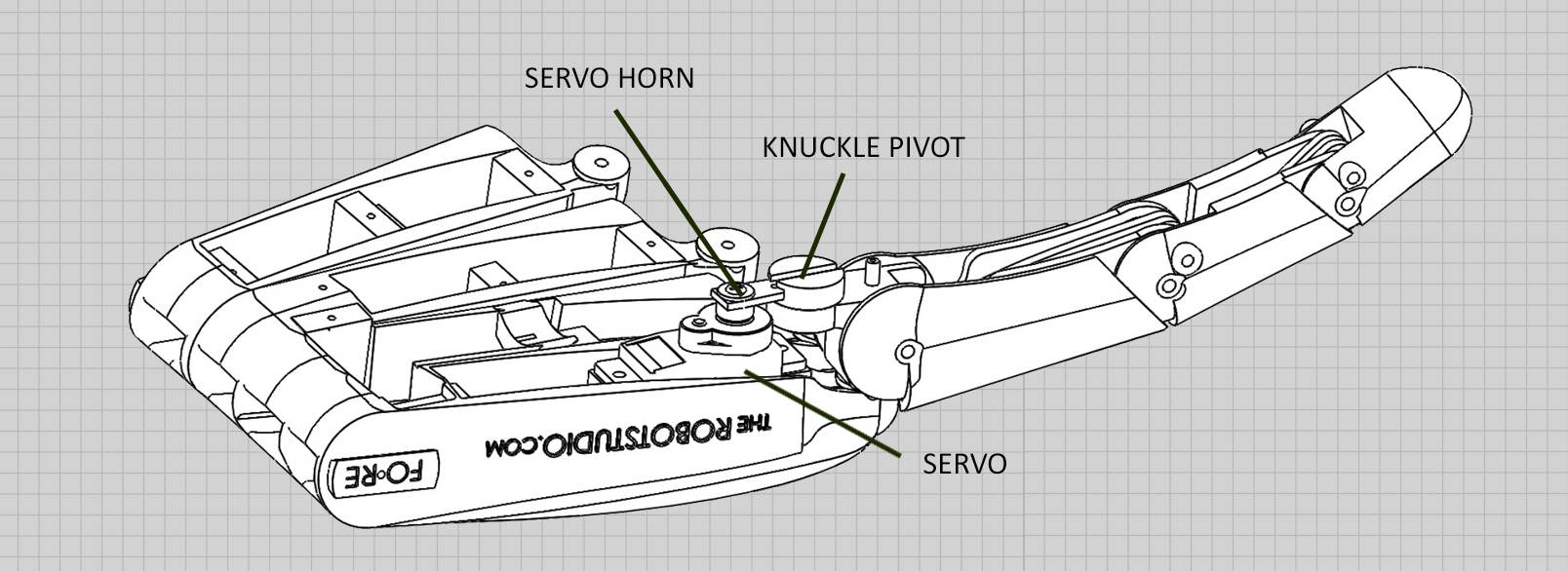
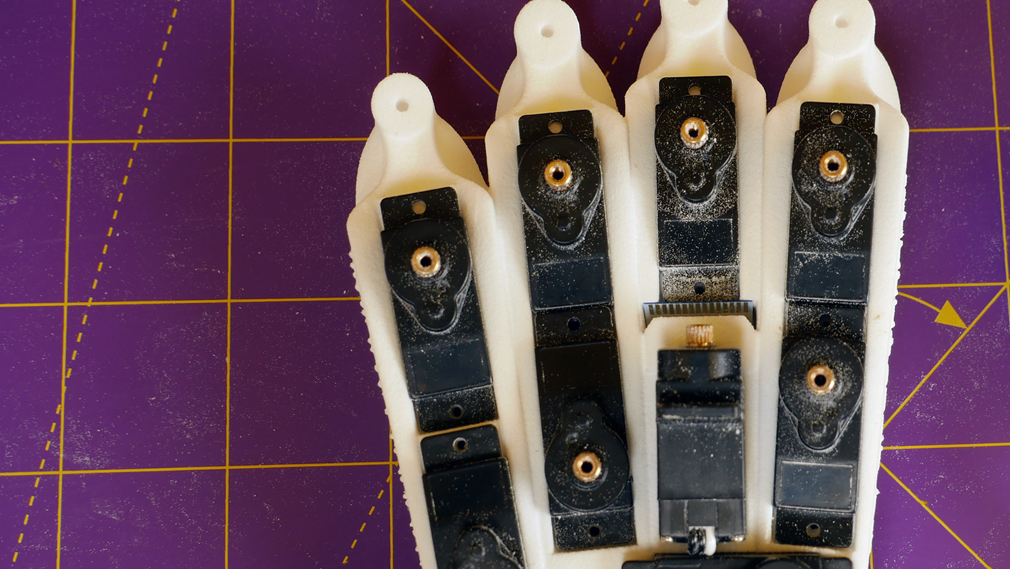
The assembled fingers are connected to the servo horns of the knuckle servos via a sliding rotational joint created by the knuckle pivot and the knuckle cross.
The knuckle cross is then mounted to the main palm print of the hand with 24mm pins.
The servo horn for the rotation of the thumb is different as it attaches directly to the thumb knuckle cross and forms one half of the base joint for the thumb.
As the pivots of the finger knuckles and the knuckle servo are a fixed distance apart, the mechanism between them must allow for a change of length as the servo horn rotates.
Connect the fingers to the knuckle servos
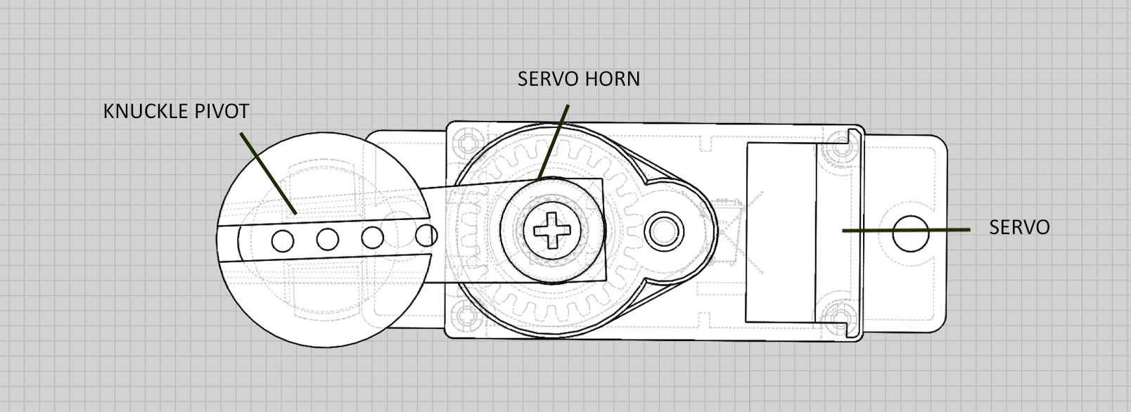
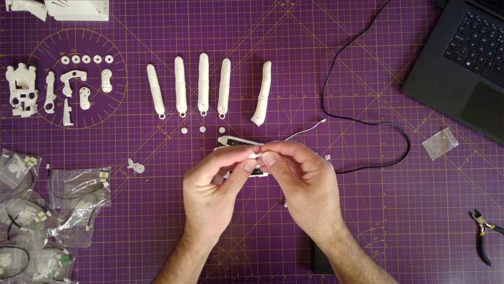
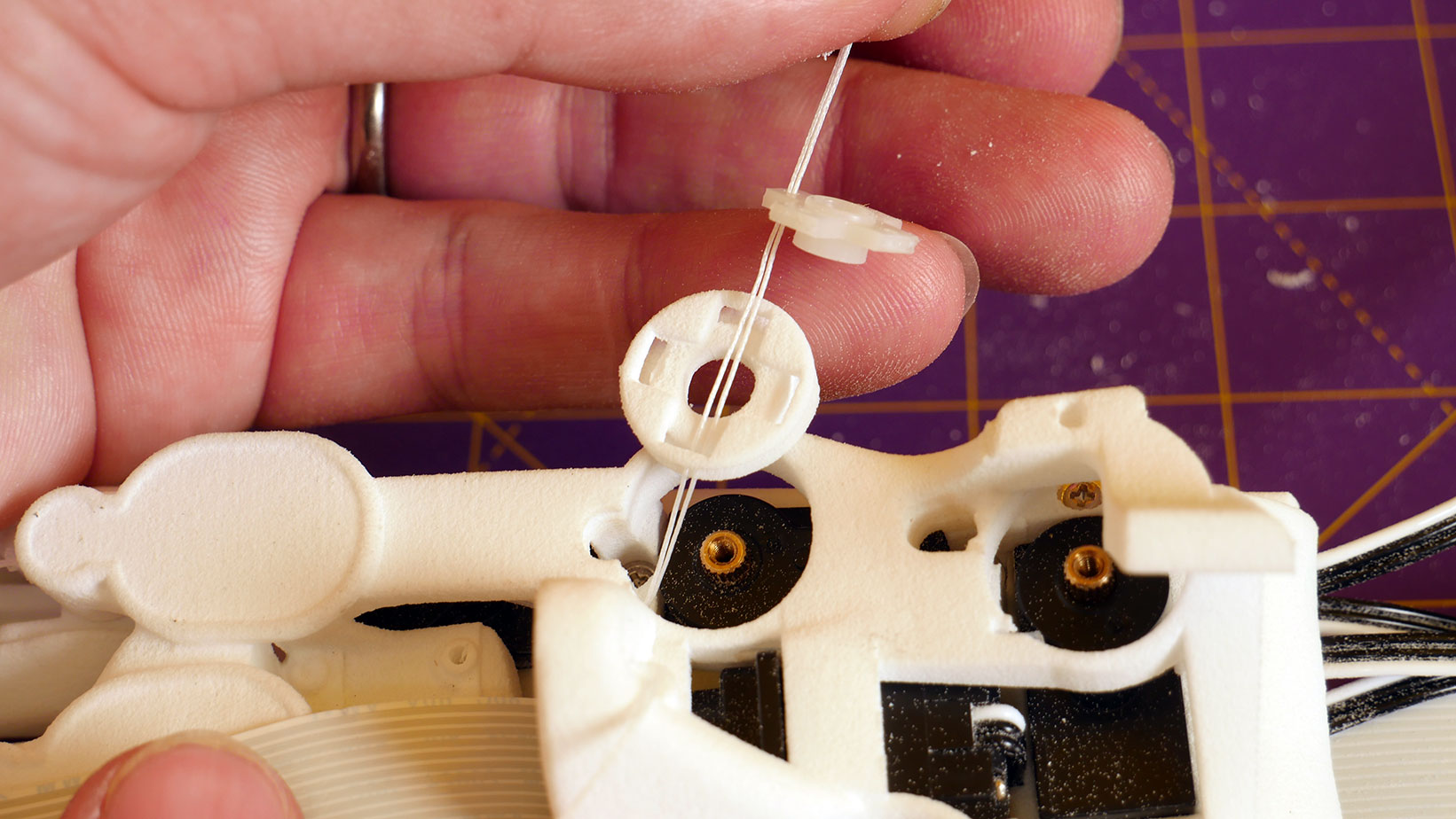
The knuckle pivot is the mushroom shaped piece that push fits into the large circular loop of the knuckle cross (1.28). - make sure it can turn freely!
NOTE: the rectangular hole through the head of the mushroom that receives the servo horn is not symmetrical (1.34) - there is a large and a small entry.
Make sure the large opening goes on to the servo horn first.
Look carefully at the diagram. The left circle is the knuckle pivot as it slides on the servo horn.
Hidden detail is shown with faint dashed lines that go left to right and these are not quite parallel.
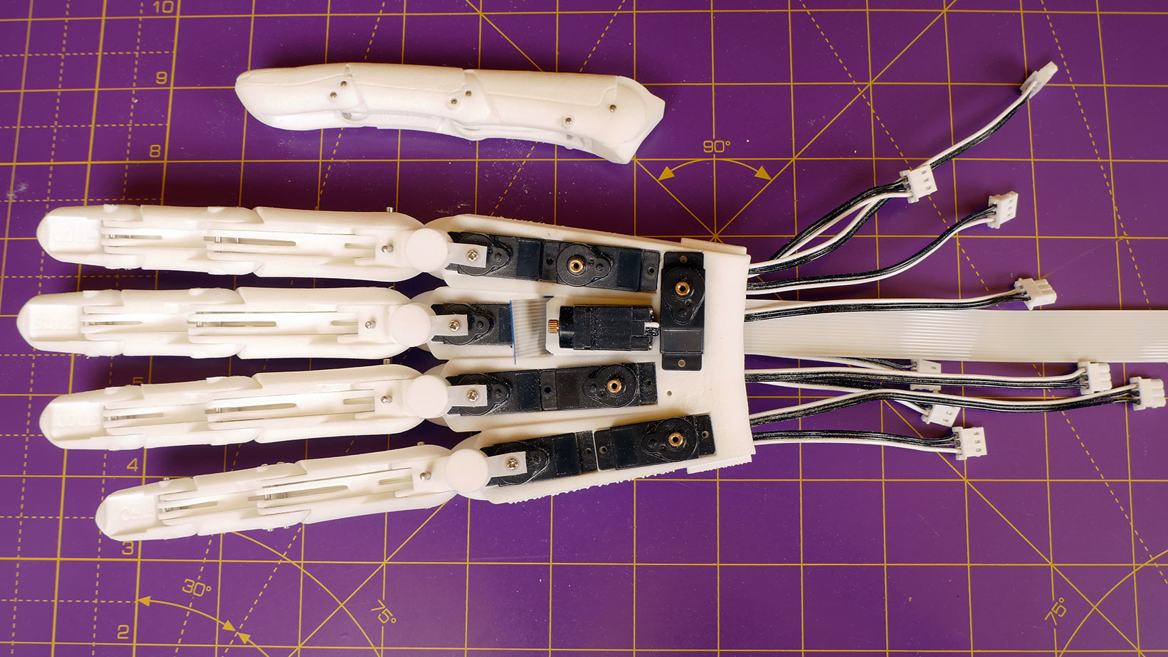
The fingers are attached to the palm by inserting a pin through hole A in the knuckle cross and pushing it into the hole in the palm (2.00).
To make the servo horn cut one arm off the double arm servo horn that is supplied with the servos (1.24).
Insert the servo horn into the knuckle pivot on the side with the larger opening and then pin the finger through hole A to the palm (2.08).
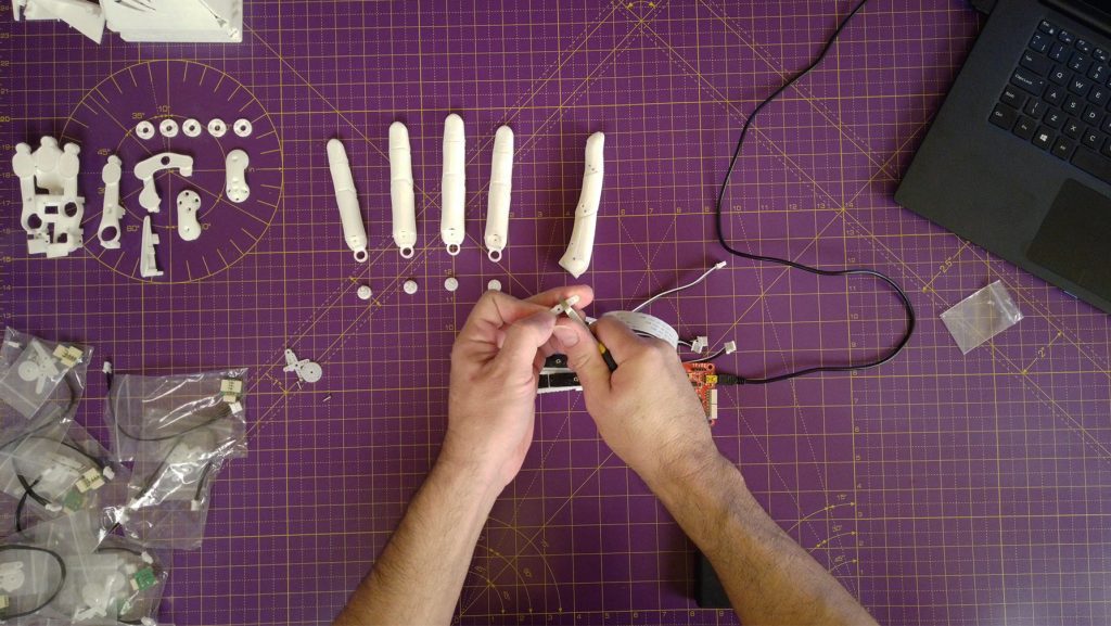
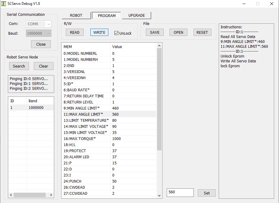
To check that everything is set up correctly drive the finger from side to side with the servo and reprogram the limits with the FT GUI as desired to prevent over rotation.
The limits are set in exactly the same way as the ID’s were changed in Step 3.
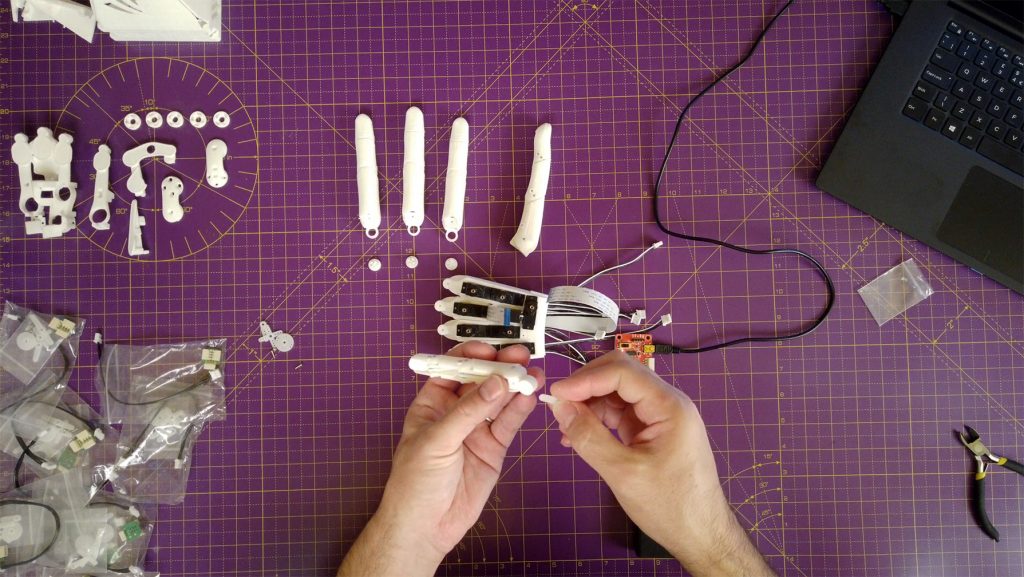
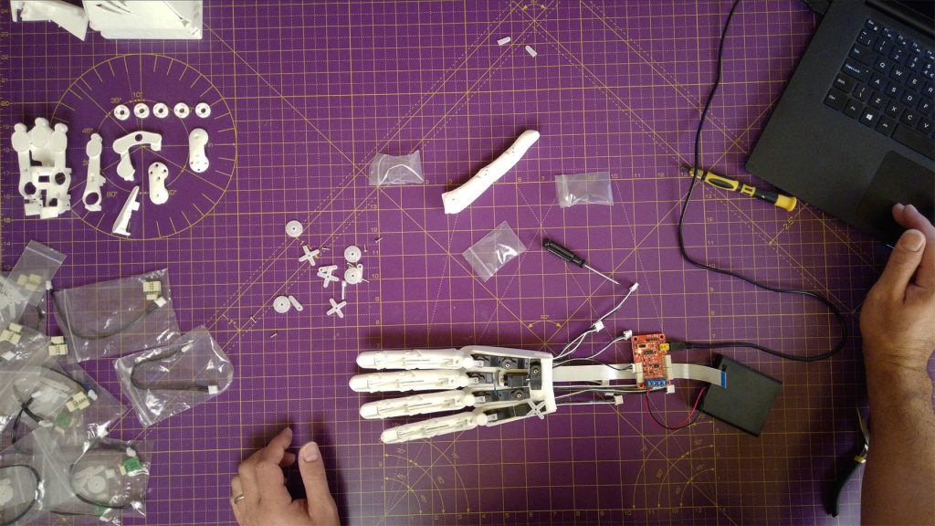
Repeat for the rest of the fingers making sure each can move side to side under command from the Feetech FT GUI.
Secure the servo horns with the screws supplied with the servos (7.42-8.35).
Mount servo 9 (Thumb Roll) to THE thumb knuckle cross
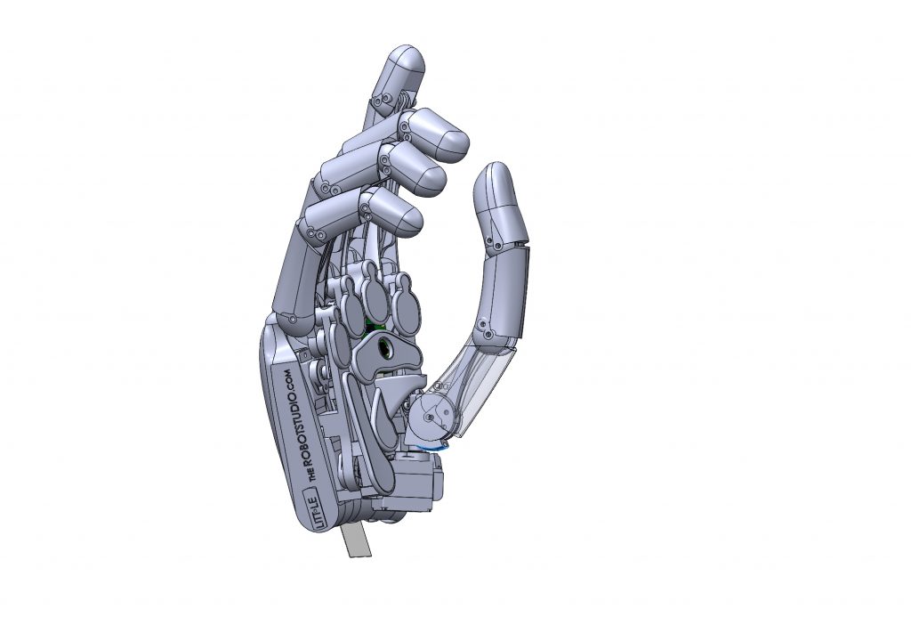
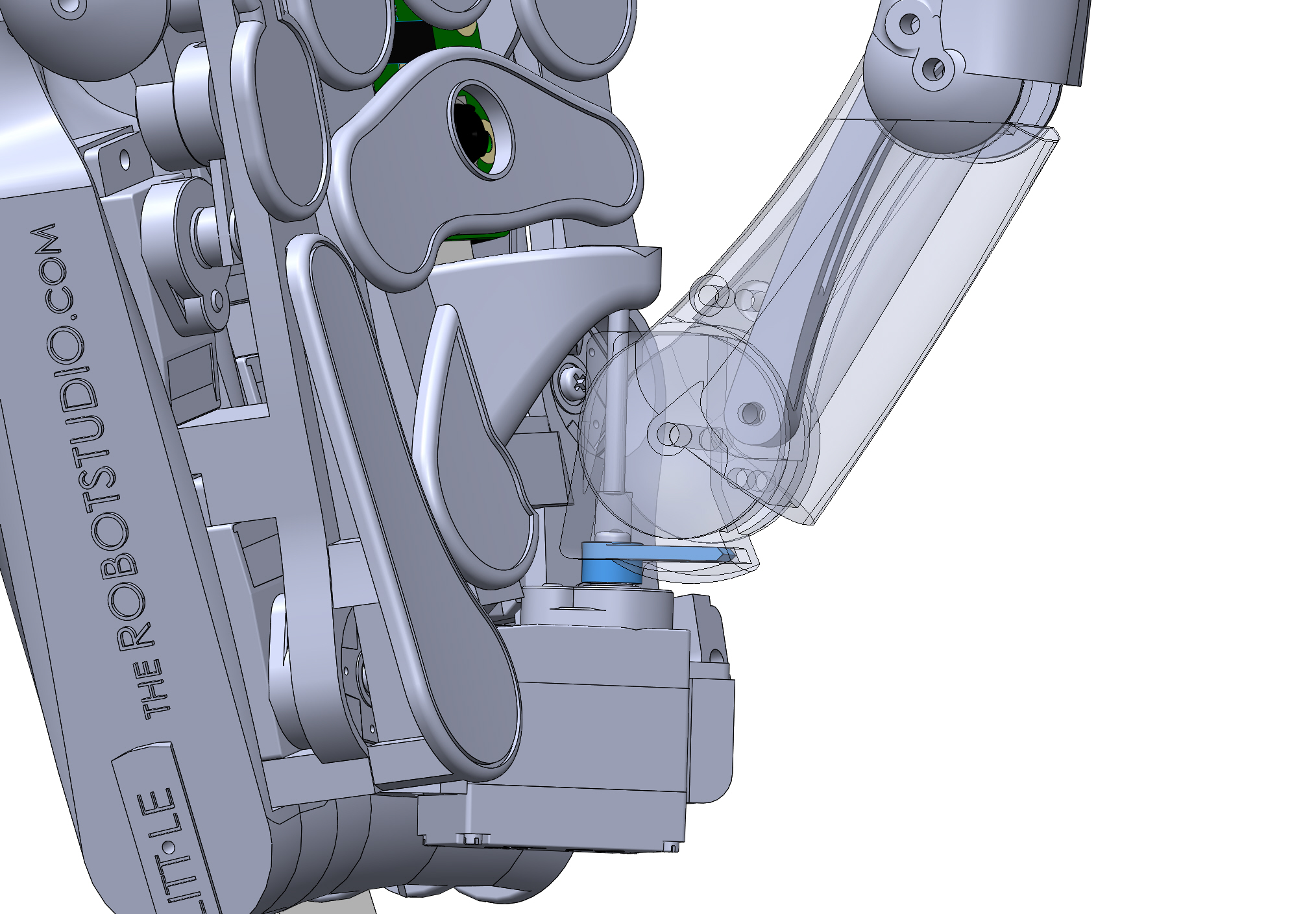
The thumb rotation is different to the fingers as the servo attaches directly to the thumb knuckle cross (10.10).
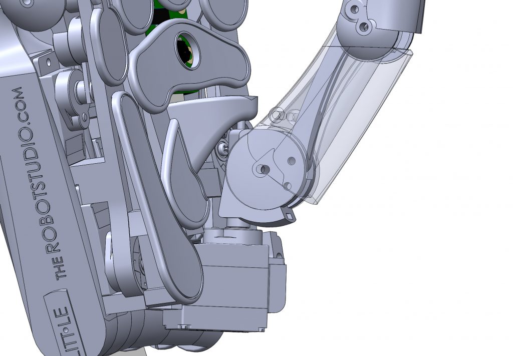
In the images that follow the assembled position of the thumb knuckle is made easier to see by making the knuckle section of the thumb transparent:
Note how the servo horn (highlighted n blue) is inserted into a rectangular tunnel in the thumb knuckle cross.
In prints done on extrusion printers, the roof of the tunnel is printed separately and secured with a screw.
Trim the single arm servo horn at the second hole from the end (11.51).
In the video the servo horn is screwed to the servo to give a stronger grip when forcing the horn into the hole (12.50).
An easier technique is just to press the servo horn into the tunnel in the TKC with a pair of pliers - should just click into place.
To be able to screw the servo horn to the servo, first insert the screw into the circular recess directly above the servo horn.
This screw can be accessed through the long hole above it - make sure to put the screw into the hole head first.
Check servo 9 has position 512 and place in the assembled position on the inner palm.
Put the thumb in the centre of the desired range and mate the servo horn with servo spline.
Use a long thin screwdriver to tighten the servo horn retaining screw through the pivot hole of the TKC.
Mount the thumb to the inner palm
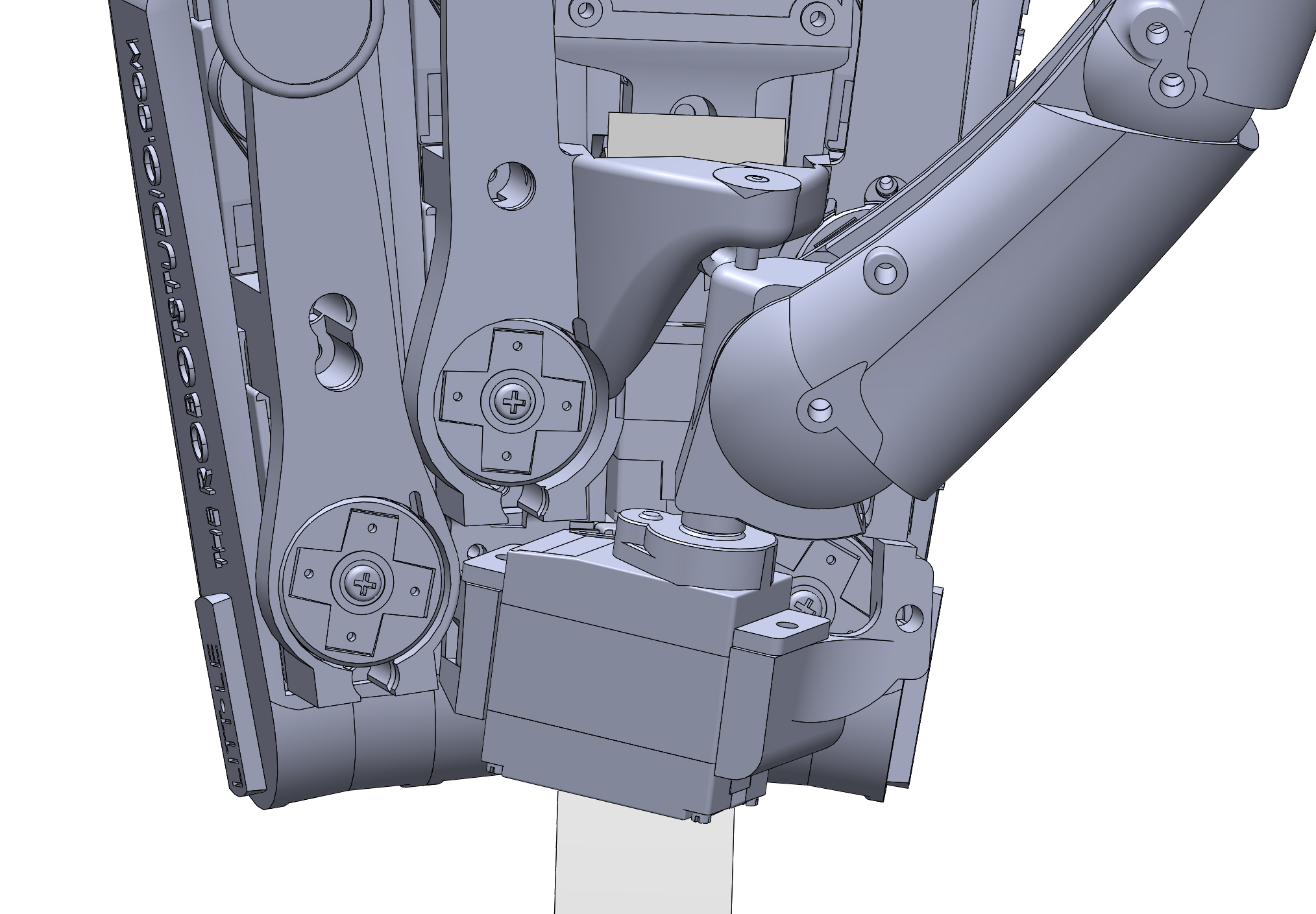
The thumb assembly can then be attached to the inner palm by two screws and a 24mm pin through the tallest part of the inner palm and the thumb knuckle cross as shown below:
First clean out the screw holesin the inner palmthat secure the servo. Ensure the screws fit easily as access is limited.
Put the thumb rollservo (9) in its final position and screw in place.
The deeper screw towards the centre of the hand is a little awkward and may need to be held in place with tweezers at the start of screwing in.
Push a pin into the thumb rollpin hole to secure the thumb knuckle cross to the inner palm.
Thread the tendon through the thumb and secure at thefinal pin as for the fingers.
Note the thumb tendon passes over the thumb rollpin towards the center of the hand.
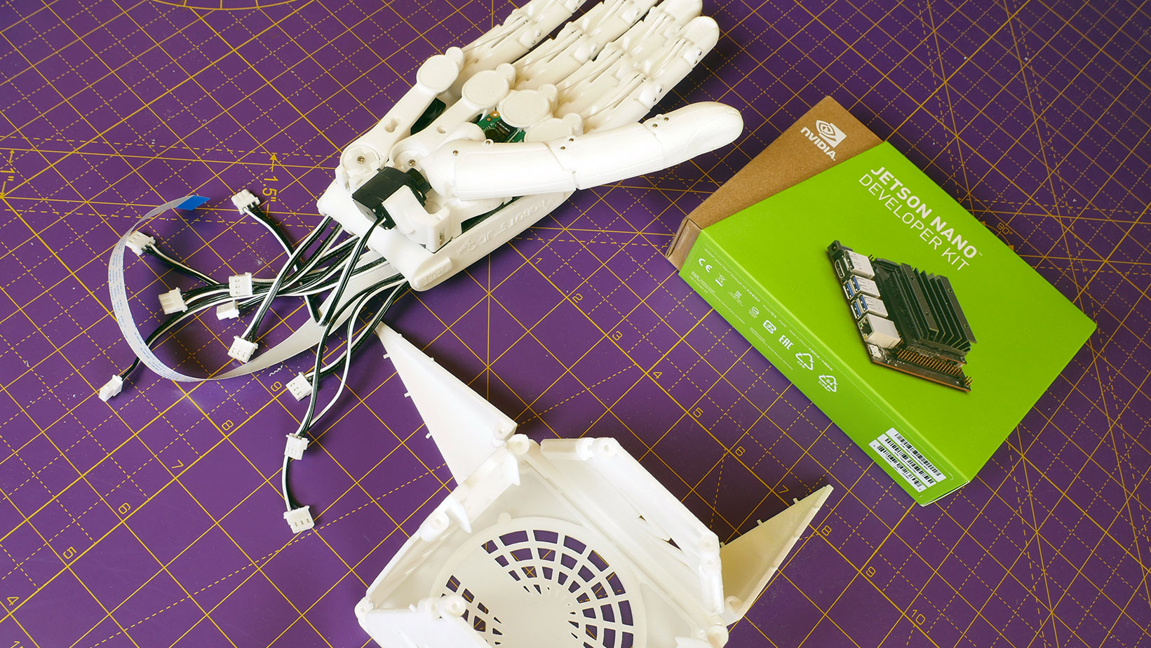
Well done! Now the fingers are attached and can rotate at the knuckles it’s time to add the tendons in Step 6.
We use cookies on our website to give you the most relevant experience by remembering your preferences and repeat visits. By clicking “Accept All”, you consent to the use of ALL the cookies. However, you may visit "Cookie Settings" to provide a controlled consent.
This website uses cookies to improve your experience while you navigate through the website. Out of these, the cookies that are categorized as necessary are stored on your browser as they are essential for the working of basic functionalities of the website. We also use third-party cookies that help us analyze and understand how you use this website. These cookies will be stored in your browser only with your consent. You also have the option to opt-out of these cookies. But opting out of some of these cookies may affect your browsing experience.
Necessary cookies are absolutely essential for the website to function properly. These cookies ensure basic functionalities and security features of the website, anonymously.
Cookie
Duration
Description
cookielawinfo-checkbox-analytics
11 months
This cookie is set by GDPR Cookie Consent plugin. The cookie is used to store the user consent for the cookies in the category "Analytics".
cookielawinfo-checkbox-functional
11 months
The cookie is set by GDPR cookie consent to record the user consent for the cookies in the category "Functional".
cookielawinfo-checkbox-necessary
11 months
This cookie is set by GDPR Cookie Consent plugin. The cookies is used to store the user consent for the cookies in the category "Necessary".
cookielawinfo-checkbox-others
11 months
This cookie is set by GDPR Cookie Consent plugin. The cookie is used to store the user consent for the cookies in the category "Other.
cookielawinfo-checkbox-performance
11 months
This cookie is set by GDPR Cookie Consent plugin. The cookie is used to store the user consent for the cookies in the category "Performance".
viewed_cookie_policy
11 months
The cookie is set by the GDPR Cookie Consent plugin and is used to store whether or not user has consented to the use of cookies. It does not store any personal data.
Functional cookies help to perform certain functionalities like sharing the content of the website on social media platforms, collect feedbacks, and other third-party features.
Performance cookies are used to understand and analyze the key performance indexes of the website which helps in delivering a better user experience for the visitors.
Analytical cookies are used to understand how visitors interact with the website. These cookies help provide information on metrics the number of visitors, bounce rate, traffic source, etc.
Advertisement cookies are used to provide visitors with relevant ads and marketing campaigns. These cookies track visitors across websites and collect information to provide customized ads.