*Please note: all software and drivers has been provided by Feetech
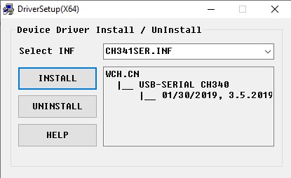
First install the driver package CH341SER.exe. Simply double click CH341SER.exe in the Windows file explorer and click INSTALL:
Next, plug in the USB on the FE-URT board (the red one in the video) and check that a single red LED comes on. The PC should also make a tone to indicate it has recognised the board as a device.
Next plug in a single SCS0009 servo to either of the white 3-pin push sockets on the opposite side of the board to the USB socket.
Observe that a second red LED comes on. (Note, plugging in the SCS15 wrist servo will not cause the second red LED to come on).
Next connect a 6v power supply to the FE-URT board at the screw terminals near to the 3-pin push sockets and observe that the second red LED goes OFF!
The screw terminal is labelled DC6V-9V – make sure to get the polarity correct! This is printed almost underneath the screw terminal – Ground is nearest to the 3-pin push sockets.
Now run the GUI by double clicking FD-v1.8(170923).exe in Windows file explorer.
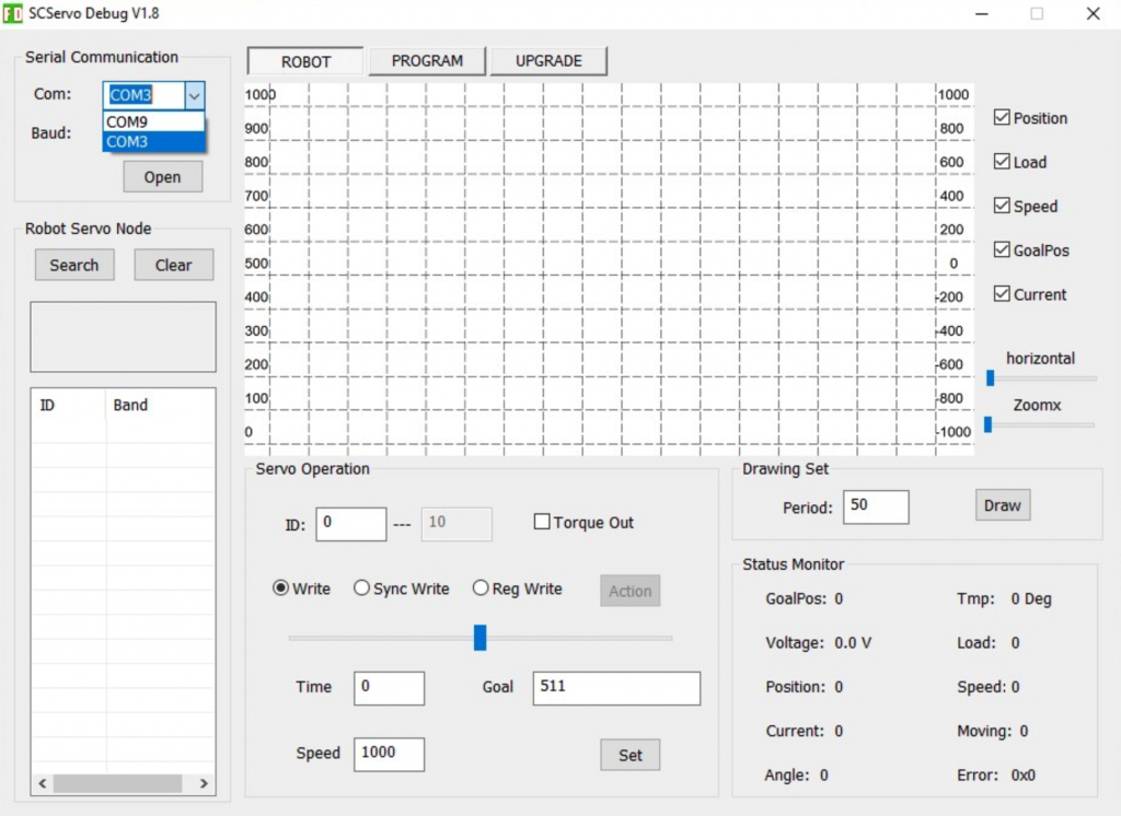
Once it opens, you should see one or more serial ports listed in the dropdown menu. In this case COM3 and COM9 but typically one low number and one high number. The high one is usually the FE-URT board. You can always check by launching the GUI with the FE-URT disconnected if not obvious.
If the GUI cannot connect to the board make sure that:
1. All the cables work and are properly plugged in.
2. All other serial devices and programs are disconnected.
3. Try reinstalling the driver.
4. Try rebooting the computer.
5. Try another computer 🙁
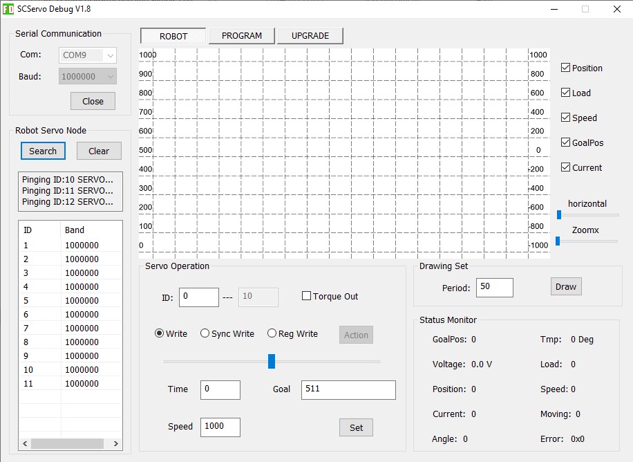
Select COM9 or similar and click open to connect to the servo.
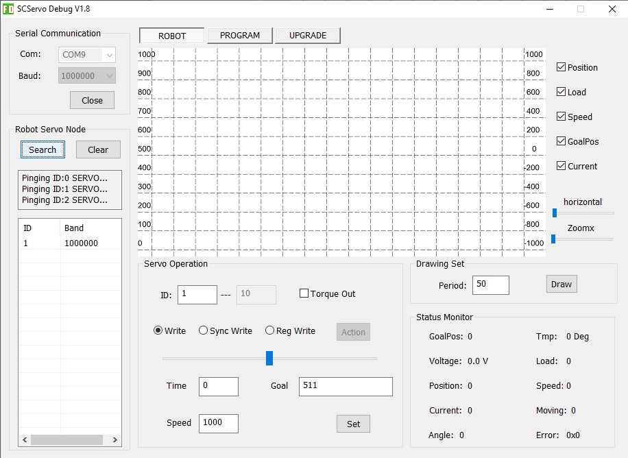
In the box labelled Robot Servo Node click the Search button and almost immediately it should find node 1.
As soon as you connect it should be possible to move the servo by typing ID 1 in the “Servo Operation” “ID:” box and moving the slider.
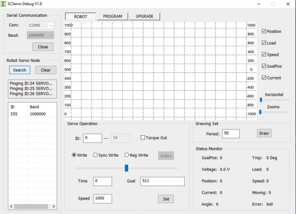
If instead you see a high servo node ID like 255 it means that the servo does not have any power supplied.
Check that the voltage going in the screw terminals on the FE-URT board is definitely 6v with the correct polarity and that all the cables are correctly plugged in.
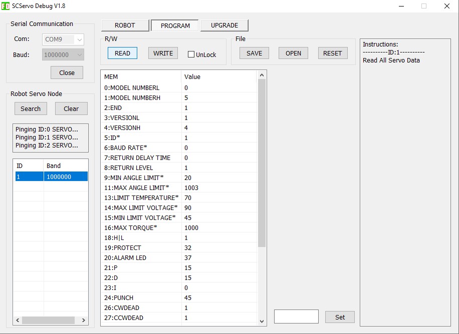
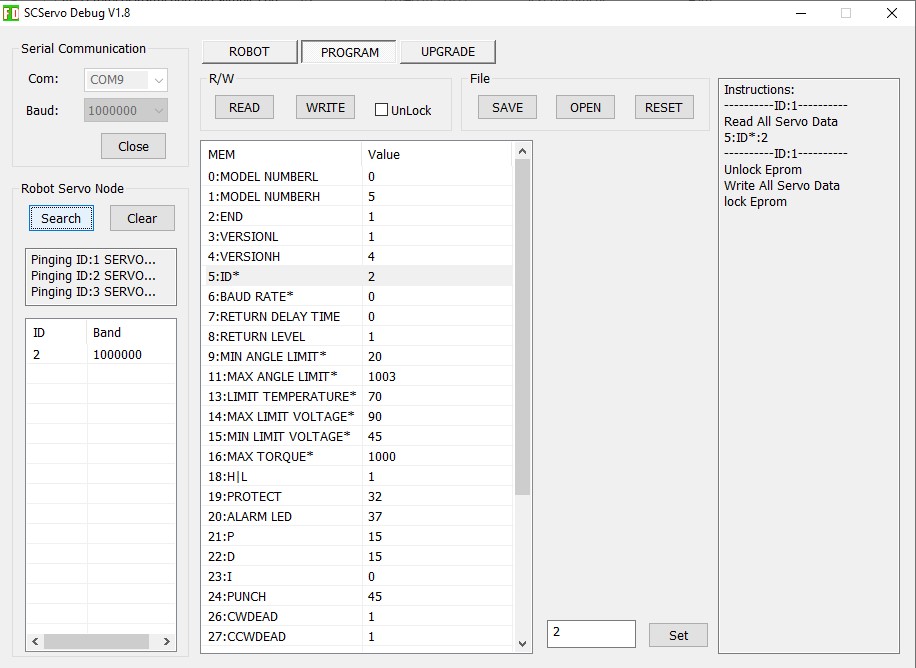
To change the servo ID, and any other settings change to the PROGRAM tab at the top of the GUI.
In the Robot Servo Node box select the servo in question and click READ in the R/W box.
It is essential to read the data first as all registers will be reprogrammed later.
Failure to do so may make a servo unusable until reprogrammed with the correct settings and parameters!
That is easy to do with servos of which you have more than one of course.
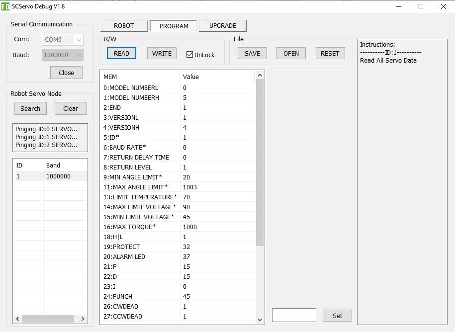
First UnLock the servo by checking UnLock in the R/W box:
Then click on the ID in line 5 of the parameters listed below the R/W box.
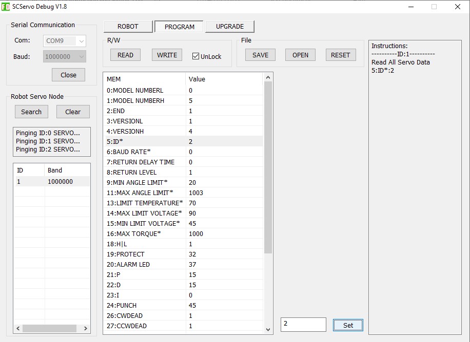
Change the number to 2 in the dialogue to the left of the set button (bottom right of the parameter window) and press the Set button.
The “Instructions:” dialogue box on the right will show 5:ID*:2
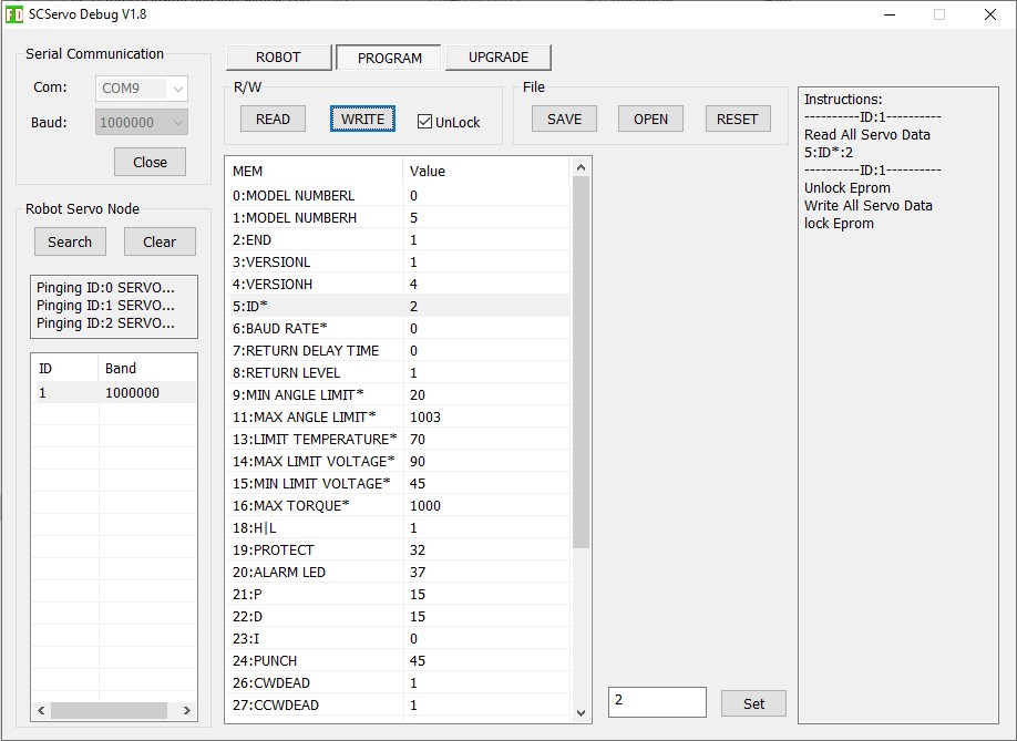
Click WRITE in the R/W box to update the servo.
Check that the dialogue box shows the same instructions as below:
Check the update has worked by clicking the Search button again in the Robot Servo Node box.
The ID found should now be 2.
On the ROBOT tab setting the servo ID to 2 should now move this servo.
Don’t forget to label the servo with the new ID!!
Program all Servos
All the servos must have different ID numbers to be able to connect to the same bus.
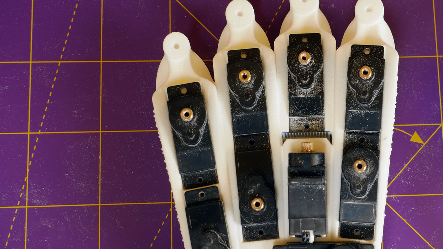
The SCS0009 servos used for the fingers have ID numbers 1-10. All odd ID numbers move a digit from side to side at the knuckle joint.
Set up the finger knuckle servos (1 – Little, 3 – Ring, 5 – Index & 7 – Fore) by moving each to position 512 on the ROBOT tab and setting the MIN ANGLE LIMIT to 450 and the MAX ANGLE LIMIT to 550 on the PROGRAM tab.
All the even ID numbers wind a tendon to make a digit contract.
Set up servos 2 and 4 by moving them to position 0. Set up tendon servos 6 and 8 by moving them to position 1023.
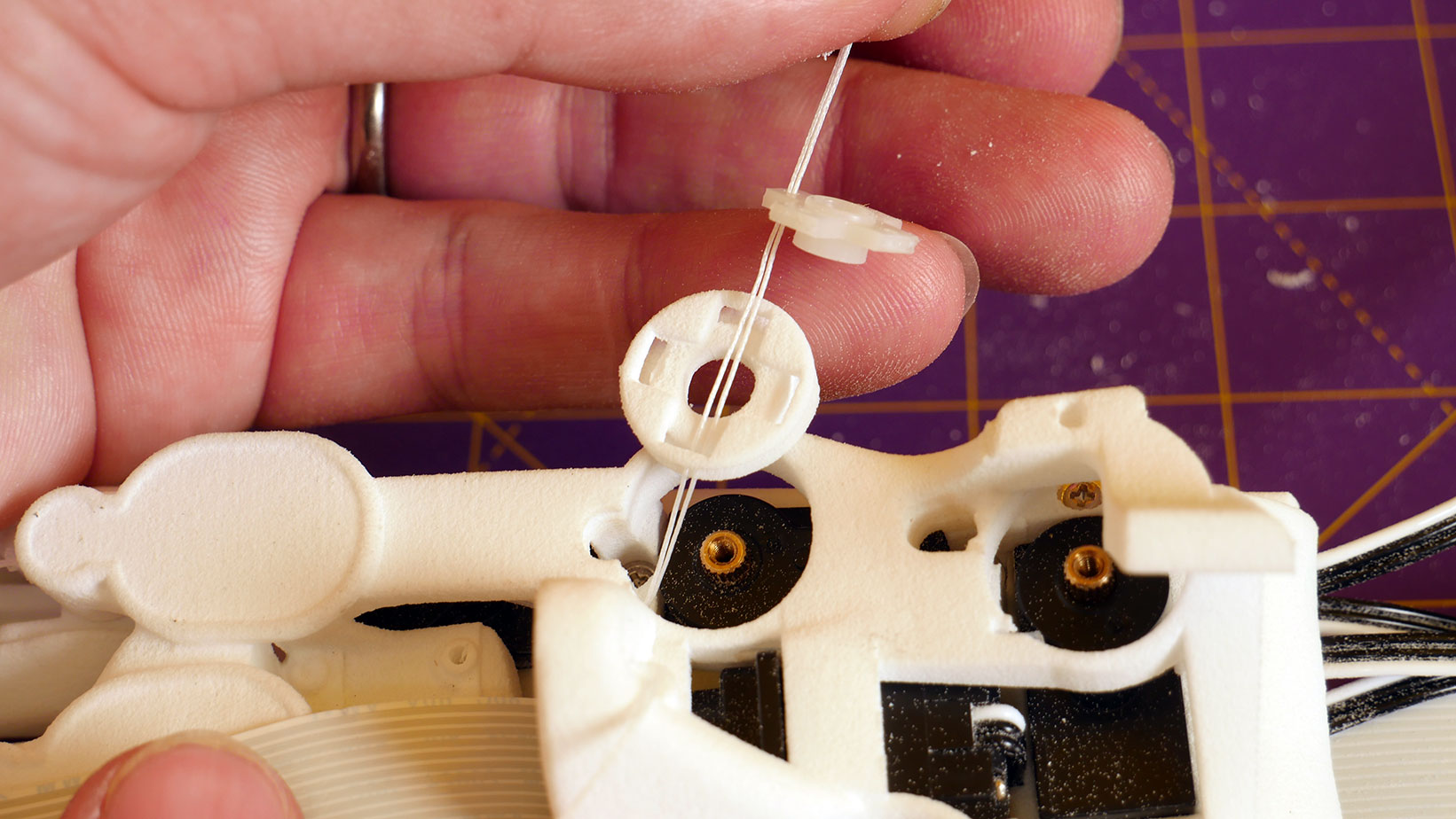
Set up the thumb roll servo (9) by moving it to position 512.
Set up the thumb tendon servo (10) by moving it to position 0.
Set up the larger SCS15 wrist servo (11) by moving it to position 512 on the ROBOT tab and setting the MIN ANGLE LIMIT to 100 and the MAX ANGLE LIMIT to 900 on the PROGRAM tab.
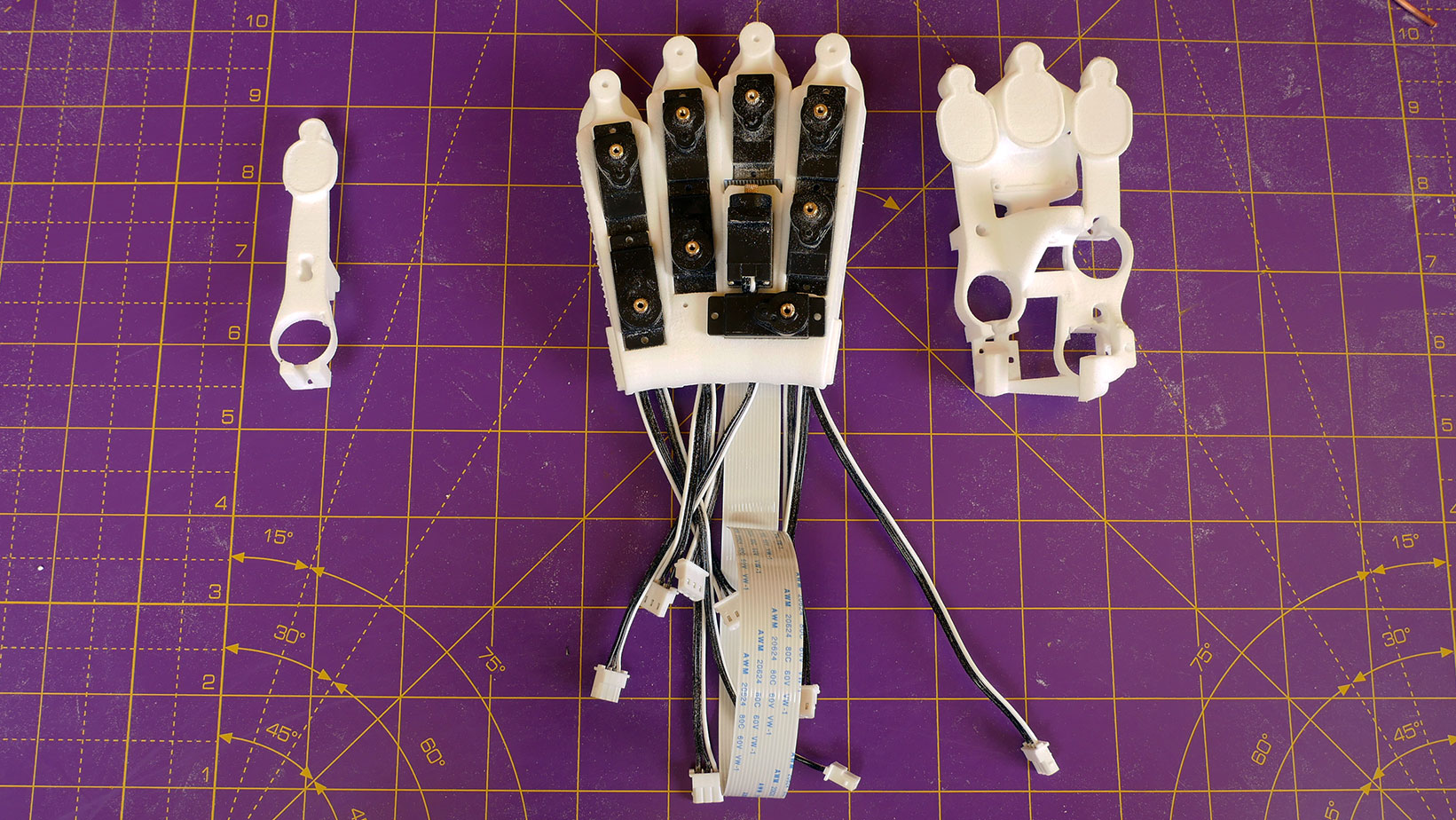
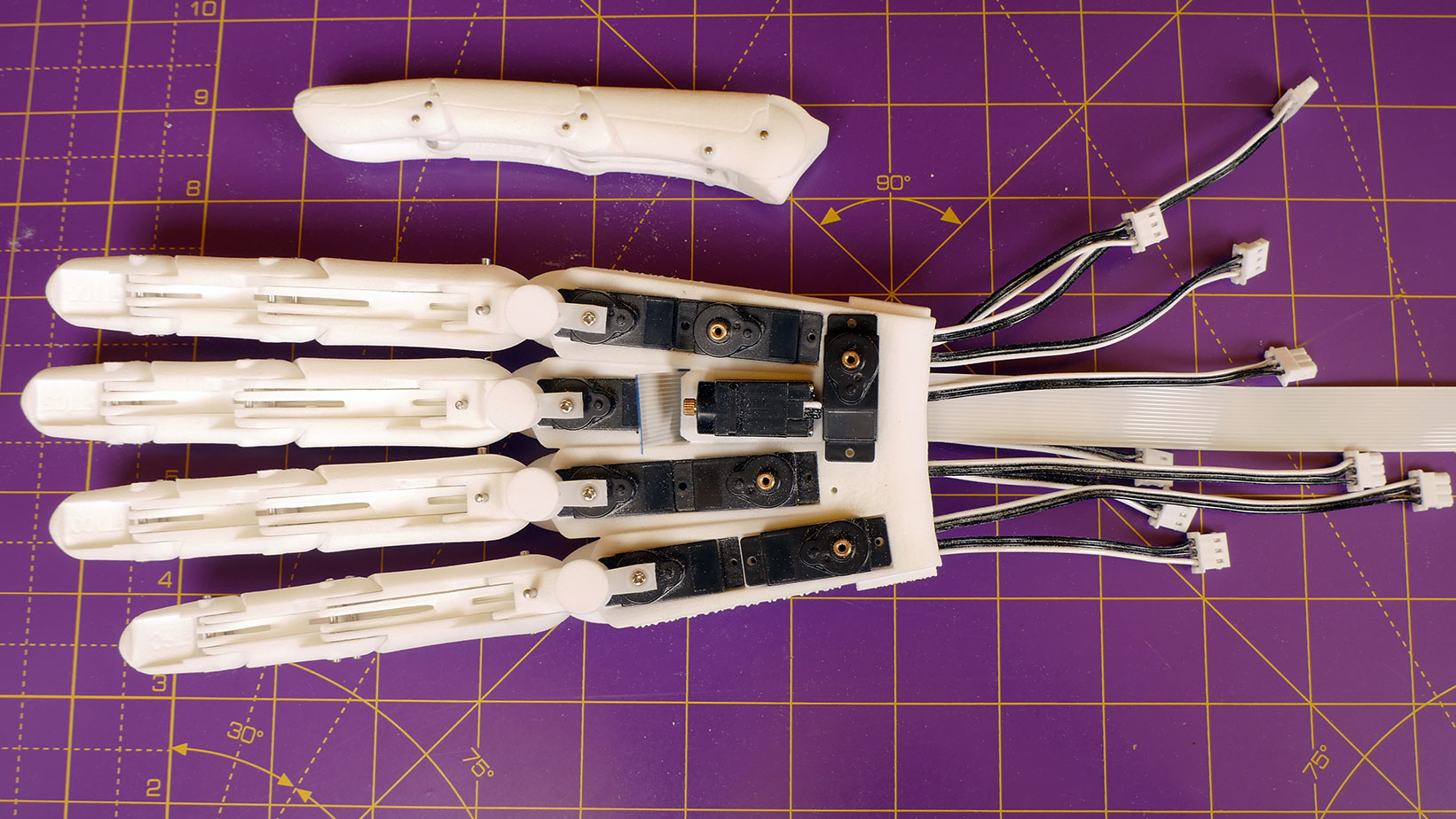
Once all the servos are programmed connect them all together with the supplied connector boards and cables.
Search again and if successful node ID’s 1 through 11 will be found and displayed in the Robot Servo Node dialogue box.
All the servos can now be moved by the slider in the ROBOT tab of the GUI.
Sync-write allows a range of servos to be controlled simultaneously.
If all eleven servos can now be controlled it is time to move on to step 4.
We use cookies on our website to give you the most relevant experience by remembering your preferences and repeat visits. By clicking “Accept All”, you consent to the use of ALL the cookies. However, you may visit "Cookie Settings" to provide a controlled consent.
This website uses cookies to improve your experience while you navigate through the website. Out of these, the cookies that are categorized as necessary are stored on your browser as they are essential for the working of basic functionalities of the website. We also use third-party cookies that help us analyze and understand how you use this website. These cookies will be stored in your browser only with your consent. You also have the option to opt-out of these cookies. But opting out of some of these cookies may affect your browsing experience.
Necessary cookies are absolutely essential for the website to function properly. These cookies ensure basic functionalities and security features of the website, anonymously.
Cookie
Duration
Description
cookielawinfo-checkbox-analytics
11 months
This cookie is set by GDPR Cookie Consent plugin. The cookie is used to store the user consent for the cookies in the category "Analytics".
cookielawinfo-checkbox-functional
11 months
The cookie is set by GDPR cookie consent to record the user consent for the cookies in the category "Functional".
cookielawinfo-checkbox-necessary
11 months
This cookie is set by GDPR Cookie Consent plugin. The cookies is used to store the user consent for the cookies in the category "Necessary".
cookielawinfo-checkbox-others
11 months
This cookie is set by GDPR Cookie Consent plugin. The cookie is used to store the user consent for the cookies in the category "Other.
cookielawinfo-checkbox-performance
11 months
This cookie is set by GDPR Cookie Consent plugin. The cookie is used to store the user consent for the cookies in the category "Performance".
viewed_cookie_policy
11 months
The cookie is set by the GDPR Cookie Consent plugin and is used to store whether or not user has consented to the use of cookies. It does not store any personal data.
Functional cookies help to perform certain functionalities like sharing the content of the website on social media platforms, collect feedbacks, and other third-party features.
Performance cookies are used to understand and analyze the key performance indexes of the website which helps in delivering a better user experience for the visitors.
Analytical cookies are used to understand how visitors interact with the website. These cookies help provide information on metrics the number of visitors, bounce rate, traffic source, etc.
Advertisement cookies are used to provide visitors with relevant ads and marketing campaigns. These cookies track visitors across websites and collect information to provide customized ads.