Step 1

Please watch video in (picture-in-picture) mode to take advantage of timestamps on each key point below

PREPARING / CLEANING 3D PRINT COMPONENTS

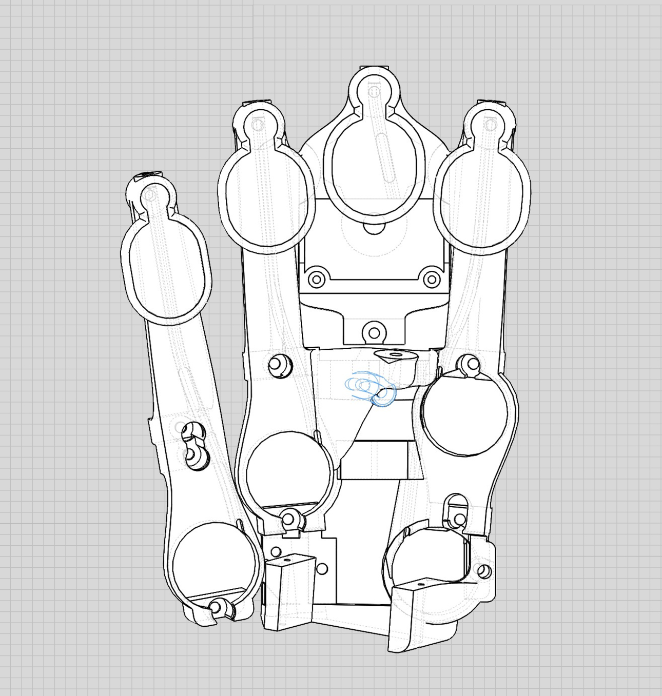
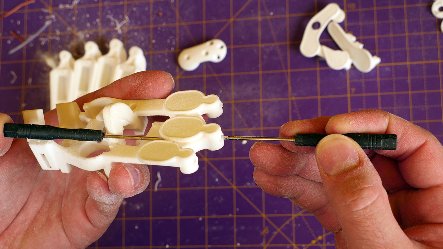
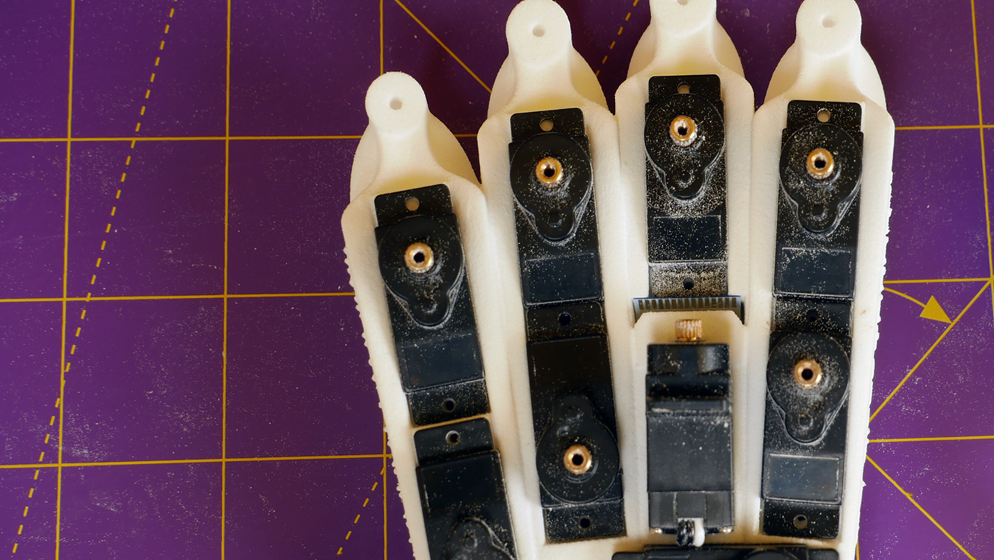
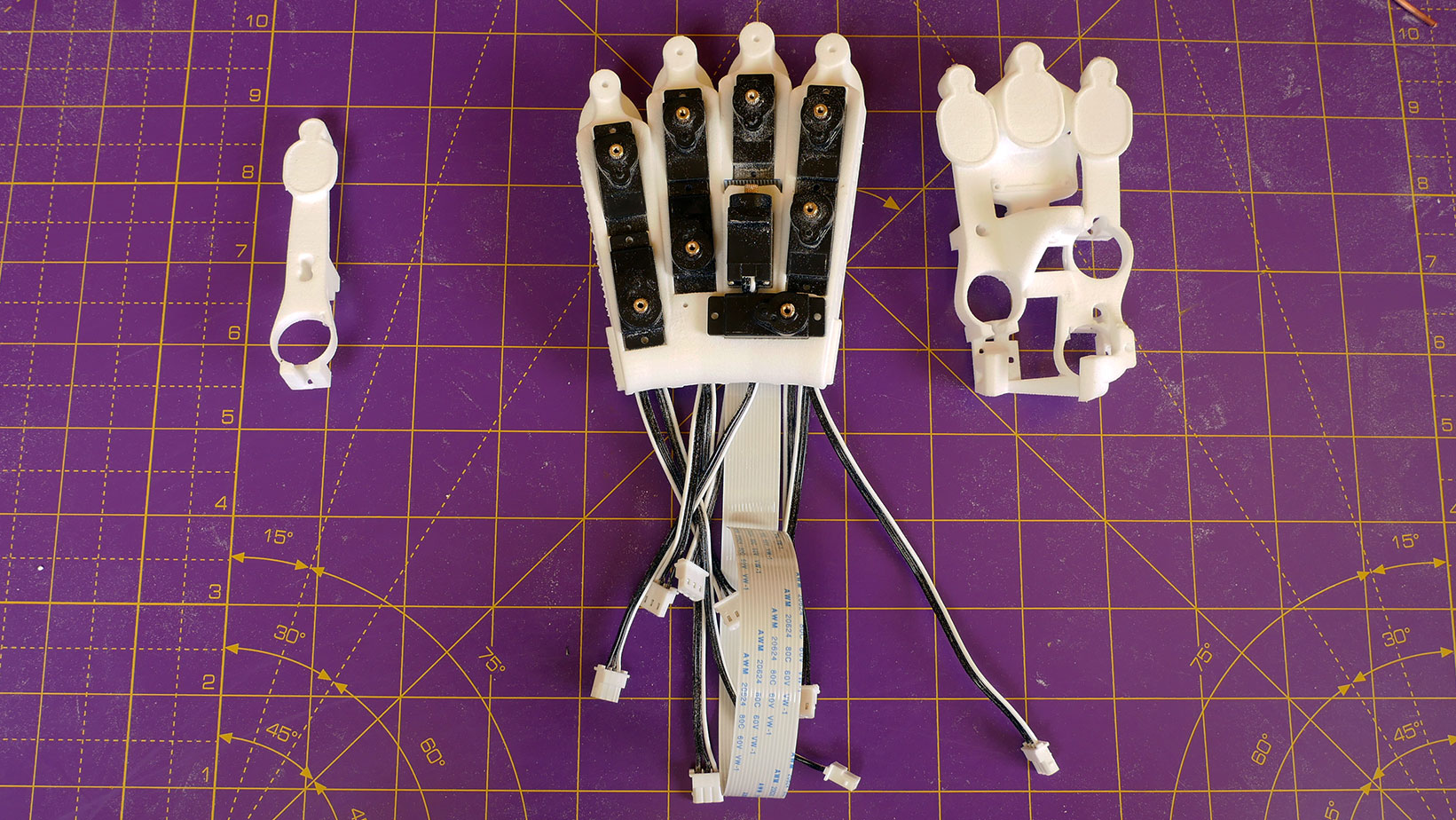
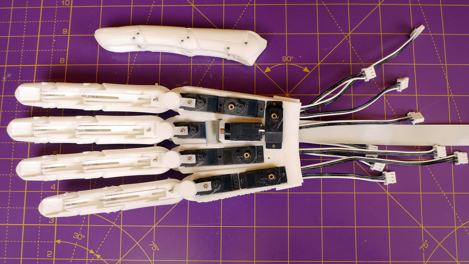
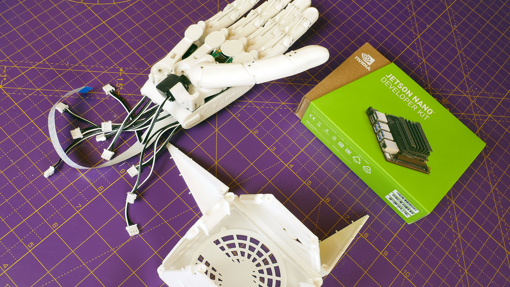
The hand is made from 3D printed parts which are held together with ground steel pins and moved by small servo motors under the control of the embedded Jetson nano. A complete list of parts is given on the home page and as a pdf here: (Click here)


To make life easier Silicon Highway sells a competitively priced kit of all the required parts and servos here: (Click here)


The easiest way to get the prints is to order them online at i.materialise.com: (Click here)


Parts ordered this way are produced by Selective Laser Sintering (SLS). This gives an excellent finish, available in a wide range of colours. All the parts are printed in an attractive box that transforms into the supporting base for the hand.


For those who prefer to print their own, the parts can also be produced on any extrusion type machine in a variety of materials such as PLA, ABS, PETG or CF nylon. A full guide on using an extrusion printer is beyond the scope of these instructions but good results have been obtained with a variety of nozzle sizes and layer thicknesses and with a little experimentation even a novice should have no problems producing the prints!


The stl files are available here: (Click here)


Before the parts can be assembled it is necessary to clean off any support material used in the production process. In the case of SLS prints this is a fine powder, for extrusion prints it is usually the same material as the print itself.


Tools needed for SLS prints:

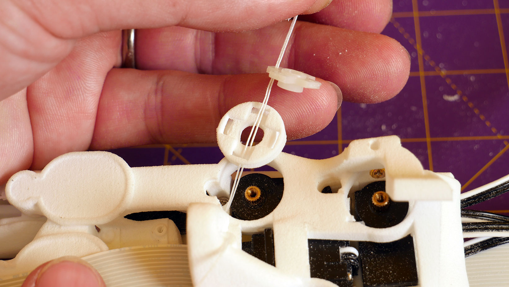
1. Small, stiff brush e.g. toothbrush – additionally a small bottle brush of the type used to clean drinking straws may be useful for cleaning out the tendon tunnels before inserting the ptfe.

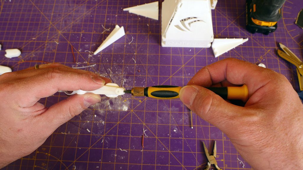
2. Small screwdriver or similar thin pokey object e.g. paperclip, bobby needle.

3. Fine engineers file, nail file or fine grit sandpaper (300 grit or finer).

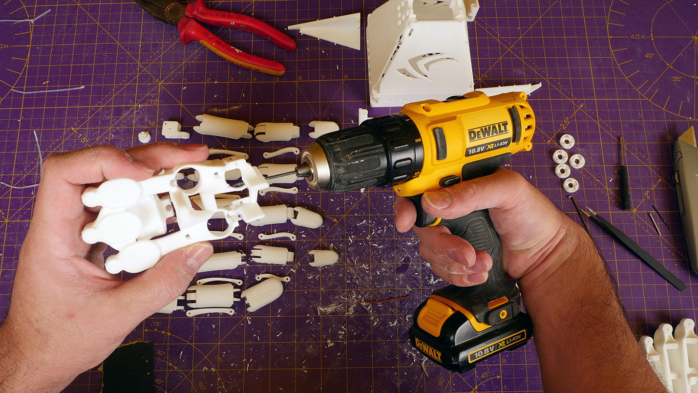
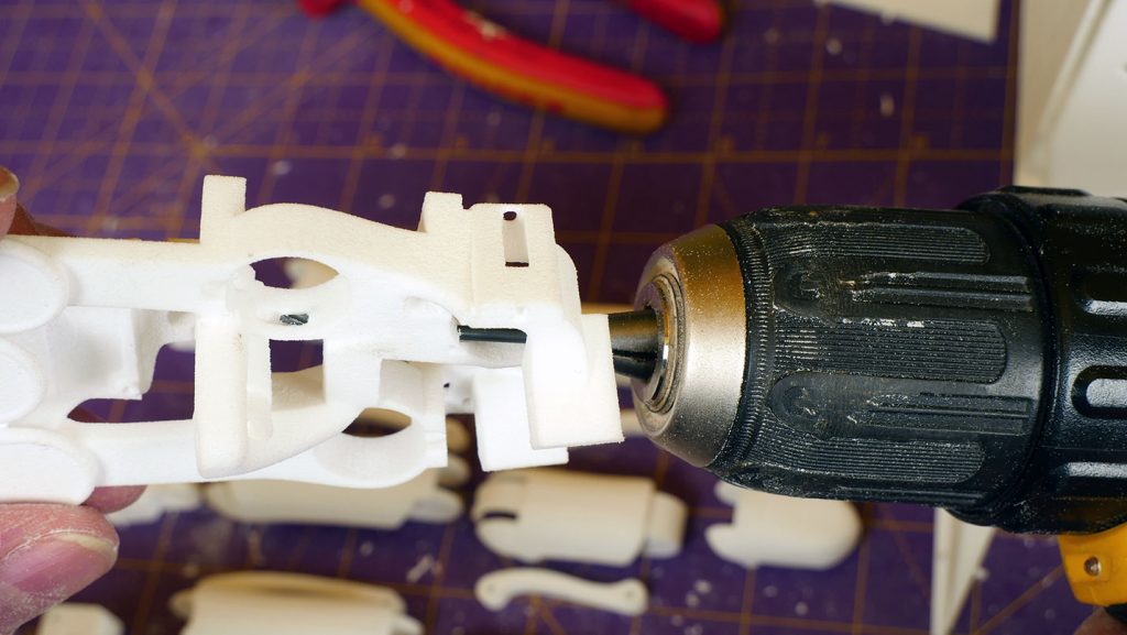
4. 2mm drill bit and hand or electric power drill.


Tools needed for FDM prints:

1. Small and medium flat blade screwdrivers.

2. Fine engineers file, nail file or fine grit sandpaper (300 grit or finer).

3. 2mm drill bit and hand or electric power drill.
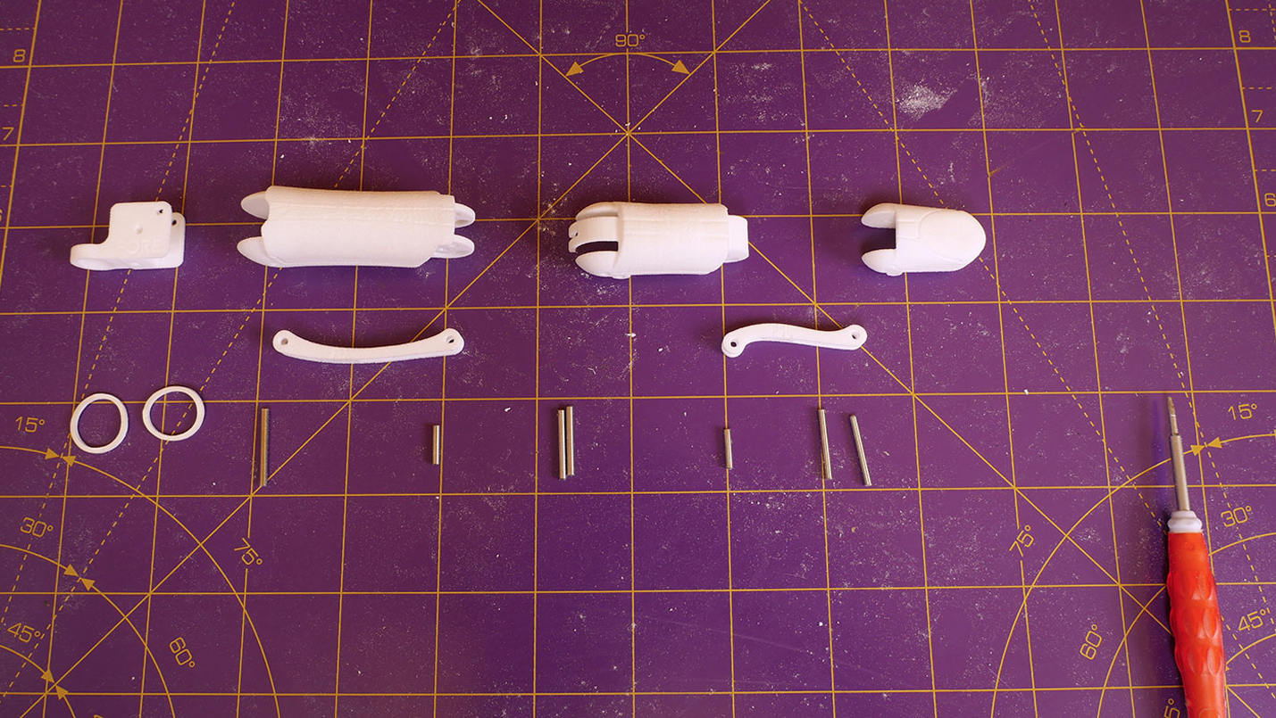
Parts needed:

1. The 3d printed parts.

2. PTFE tubing – 1mm internal diameter (ID) by 2mm outer diameter (OD).

Remove all powder or supports

Before assembling the printed parts they must be thoroughly cleaned of any support material used during printing. How long that takes depends considerably on the printing technology and material selected.


SLS prints use a powder as a support material which is largely removed at the factory with any residue easily removed with a stiff brush like a toothbrush (0:12) and a paperclip or screwdriver (1:35) for getting into the corners.

A fair amount of dust may still be produced! (3:30)

Extrusion printers normally use the same material as the print for support material. How difficult it is to remove varies according to material, orientation of the piece during printing and the skill of the operator.


Regardless of printing material, the sections need to be cleaned until they rotate freely against each other or the elastic band will struggle to fully extend the finger.


IMPORTANT! A good test is to hold the two sections of a finger joint together in the assembled position and then release one side. If that section doesn't fall away from gravity alone, then the joint is not yet free enough!


Additionally, clean the inside surfaces of the knuckle and middle finger sections where the linkages will slide and the concave recesses where the joints overlap.


The sections of finger can be identified by their relative size and in SLS prints by labels engraved on the inside of each section. There are three sizes of finger parts as the ring and fore finger are the same size and defined as the standard size of 100%. The index finger is 105% and the little finger 90% size.


The letters are simple abbreviations: F for finger, T for Thumb, K for Knuckle, M for Middle section and T for Tip section. Hence FK100 is the knuckle section for the fore and ring fingers.


The easiest way to sort the finger parts is to gather each group of four similar parts together and then arrange them by size. (1.30) The index finger is the largest, next the ring and fore finger (which are the same size), then the little finger which is the smallest.


The only exception are the knuckle crosses as the ring and fore have a slightly different offset from the bottom face to the loop.


These can be identified by a single letter which is engraved into the underside – F for Fore finger, I for Index finger, R for Ring finger and L for the little finger – these will also help later when attaching the assembled fingers to the palm.


The parts for the thumb are much wider than the finger sections, particularly at the tip, and the thumb knuckle cross (TKC) has a completely different shape without a loop.

Clean the base parts


The legs of the base (4.45) form the top corners of the containing box for SLS prints and are held on by a series of little cylinders. These cylinders taper a little before joining to the main pieces so should break or cut away easily.


The base box should be carefully cut apart with a craft knife (4.25).

The golden rule with blades is: NEVER CUT TOWARDS YOURSELF!

To prepare the parts of the base box trim away all the small cylindrical supports and clean out the holes at each corner that receive the pins.


The only point to take care of is where the pyramid is pinned together at the top – there is a small stop at the bottom of the hinge on the front and back panels – take care not to drill this out by mistake!

Clean out the tendon tunnels


Each tendon passes from the tendon servos to the digit it contracts through a tunnel in the inner palm.


To ensure smooth operation and long tendon life these tunnels work best when lined with ptfe tubing (1mm internal diameter by 2mm outer diameter).

To open the tunnels in the two inner palm prints use a straight length of wire or if necessary a 2mm drill taking care not to exceed the depth of any straight sections (7.00).

If the ptfe tube doesn't pass easily use a miniature bottle brush of the type used to clean stainless steel drinking straws, a length of printing filament (10.48) or the ptfe itself with the end cut an angle (7.40).

The path of each tendon tunnel passes through the middle of the inner palm structures and can be accessed from either end to make cleaning out easier.


The tunnels for each finger are shown below highlighted in blue with the inner palm in the position it occupies when the hand is palm downwards.

This is the the path of the little finger:

This is the ring finger:

This is the index finger, note how far back it extends:

This is the fore finger:

With the inner palm flipped over the tendon tunnel for the thumb is upright in the middle:

Fit ptfe tubing to inner palm structures 

Once all the tendon tunnels have been cleaned out, pass a length of ptfe tubing all the way through the tunnel.


Once cleaned out the tunnels should easily receive the ptfe liner.


The miniature bottle brushes that are used for cleaning metal drinking straws are useful to widen the tunnels if necessary – the ptfe should fit easily not too tight to push in, yet securely held in place.


If necessary there are two additional techniques to fit ptfe liners in an awkward tunnel by forcing it past tight spots.


Wire: fit a wire with a crimp and slide on the ptfe, then thread the other end through the tunnel first. The wire can then be used to pull the ptfe liner into the tunnel – a series of sharp pulls often works best.


Nose: By stretching a length of ptfe until it starts to neck it is possible to put a long thin nose on the end that can be passed through tight spots and then pulled from the other of the tightspot with pliers.


Alternatively if the ptfe is loose in the tunnels it can be secured by flaring open each end of the cut tube with any conical tool. Ideally use a pair of dot punches but screwdrivers will also suffice:

Drill all clearance holes

The finger sections are held together and can rotate freely to each other around pins. Ideally these are made of ground steel but for a quick trial 1.75mm filament also does the job nicely and can be easily fixed in place by melting and flattening the ends.

To ensure a smooth finger movement check every hole that receives a pin and if necessary clean out with a 2mm drill (4.55).

Each pin that forms a rotational joint will have some holes that are a tight fit and some that are loose. Holes on the inside of a joint are loose and all holes on the outside are tight so take care not to over drill the outer holes as the pins may fall out.

If pins do become loose they can be retained by gently heating the plastic at the edge of the hole and slightly deforming it.

The inner holes should be sufficiently loose that the part spins freely around the pin when flicked. Take care not to open these holes up too much or the joint will become inaccurate.

Once you have completed cleaning the 3d printed parts so all the joints can move freely and have installed the ptfe tubing in the five tendon tunnels, it’s time for step 2.